Complementary analog bipolar transistors with trench-constrained isolation diffusion

Inactive Publication Date: 2005-09-13
ADVANCED ANALOGIC TECHNOLOGIES INCORPORATED
View PDF8 Cites 92 Cited by
  • Summary
  • Abstract
  • Description
  • Claims
  • Application Information

AI Technical Summary

Benefits of technology

[0041]This process is particularly useful in constructing relatively high-voltage devices in an epitaxial layer. Bipolar transistor devices, rated for reliable operation at a 20V operating voltage, for example, which would typically require a breakdown voltage in the range of 60V to 70V. This requires a relatively thick epitaxial layer and deep diffusions extending through the epitaxial layer to isolate the devices electrically from the substrate or from each other. The isolation is provided by a reverse-biased PN junction. In conventional technology, these deep diffusions require a substantial thermal budget (a product of temperature and time), which also causes the diffusions to spread laterally and increases the size of the devices, limiting the number of devices that can be placed in a given area of the wafer.
[0042]Using the principles of this invention, the lateral expansion of the diffusion is limited because the diffusivity of the dopant in the dielectric material in the trench is typically less than the diffusivity of the dopant in the semiconductor substrate or epitaxial layer. Furthermore the dopant after having diffused into the dielectric of the trench, is not electrically active and does not affect or influence the junction breakdown of neighboring junctions

Problems solved by technology

In conventional technology, these deep diffusions require a substantial thermal budget (a product of temperature and time), which also causes the d

Method used


Image

  • Complementary analog bipolar transistors with trench-constrained isolation diffusion
  • Complementary analog bipolar transistors with trench-constrained isolation diffusion
  • Complementary analog bipolar transistors with trench-constrained isolation diffusion

Examples


Example

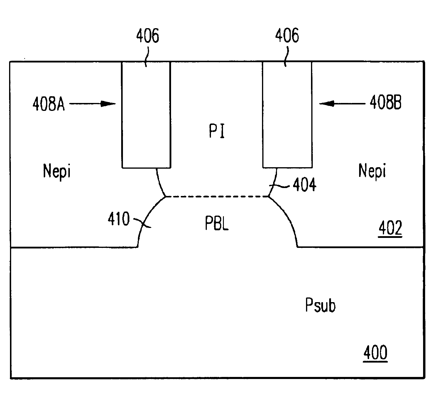
[0078]FIG. 12 illustrates a basic example of the structure and process of this invention.

[0079]An N epi layer 402 has been grown on a P substrate 400, and a P-type dopant, such as boron, has been implanted through the top surface of N epi layer 402 to form a P isolation region 404. Trenches 408A and 408B have been formed in N epi layer 402 on opposite sides of P region 404. Trenches 408A and 408B are filled with a dielectric material 406, which may be an oxide, nitride or multiple layers of different types of dielectrics.

[0080]During a thermal process, as the P-type dopant in isolation region 404 diffuses downward, trenches 408A and 408B act as barriers to the lateral spreading of the dopant. The diffusivity of the dopant is generally lower in dielectric material 406 than in N epi layer 402. This limits the lateral spreading of the dopant. In turn, the resulting increased concentration of P-type dopant between trenches 408A and 408B tends to increase the gradient of the dopant conce...


PUM


Abstract

A semiconductor substrate includes a pair of trenches filled with a dielectric material. Dopant introduced into the mesa between the trenches is limited from diffusing laterally when the substrate is subjected to thermal processing. Therefore, semiconductor devices can be spaced more closely together on the substrate, and the packing density of the devices can be increased. Also trench constrained doped region diffuse faster and deeper than unconstrained diffusions, thereby reducing the time and temperature needed to complete a desired depth diffusion. The technique may be used for semiconductor devices such as bipolar transistors as well as isolation regions that electrically isolate the devices from each other. In one group of embodiments, a buried layer is formed at an interface between an epitaxial layer and a substrate, at a location generally below the dopant in the mesa. When the substrate is subjected to thermal processing, the buried layer diffuses upward, the dopant in the mesa diffuses downward until the two dopants merge to form an isolation region or a sinker extending downward from the surface of the epitaxial layer to the buried layer. In another embodiment, dopant is implanted between dielectrically filled trenches at a high energy up to several MeV, then diffused, combining the benefits of deep implantation and trenched constrained diffusion to achive deep diffusions with a minimal thermal budget.

Description

FIELD OF THE INVENTION[0001]This invention relates to an isolation structure for junction-isolated integrated semiconductor devices, and in particular complementary analog bipolar (CAB) transistors, and a method of forming the same.BACKGROUND OF THE INVENTION[0002]As the minimum feature sizes in integrated circuits become smaller, it becomes necessary to increase the packing density of the devices on the integrated circuit (IC) chip. The benefits of smaller devices are largely forfeited if the distance between devices cannot also be decreased.[0003]FIGS. 1-11 illustrate prior art processes and structures and some of the problems that are inherent in those processes and structures.[0004]FIG. 1A illustrates a common method of fabricating a semiconductor device. A dopant is introduced in an N or P substrate 100 through an opening formed in a mask layer 102, which could be an oxide, a nitride, photoresist, or some combination thereof. The dopant could be introduced by ion implantation o...

Claims


Application Information

Patent Timeline
IPC IPC(8): H01L21/70H01L21/331H01L21/02H01L21/8249H01L21/8228H01L21/8224H01L27/06H01L27/082H01L21/76H01L21/8222H01L21/8234H01L21/8248H01L27/088H01L29/73H01L29/732
CPCH01L21/8224H01L21/82285H01L27/0821H01L27/0826H01L29/6625H01L29/66272H01L2924/0002H01L2924/00H01L21/76H01L29/70H01L29/73
Inventor WILLIAMS, RICHARD K.CORNELL, MICHAEL E.CHAN, WAI TIEN
Owner ADVANCED ANALOGIC TECHNOLOGIES INCORPORATED
Why Eureka
Try Eureka