Auxiliary air supplying system, and control methods and failure diagnostic methods thereof

a technology of auxiliary air supply and control method, which is applied in the direction of engine components, mechanical equipment, machines/engines, etc., can solve the problems of inability to accurately discriminate anomalies due to freezing, difficulty in accurately determining which components have anomalies of what kind, and inability to detect anomalies, etc., to prevent wasteful purging, suppress emission degradation, and improve discrimination accuracy

Inactive Publication Date: 2005-09-20
TOYOTA JIDOSHA KK
View PDF18 Cites 31 Cited by
  • Summary
  • Abstract
  • Description
  • Claims
  • Application Information

AI Technical Summary

Benefits of technology

[0016]It is preferable to purge the auxiliary air inlet line according to the result of the failure diagnosis. By performing the failure diagnosis and then purging the auxiliary air inlet line according to the result of the diagnosis, it is feasible to prevent wasteful purge, i.e., excessive auxiliary air supply, thereby suppressing degradation of emission. On the other hand, if condensed water remains, it can be securely discharged by the purge, so that freezing thereof can be prevented du

Problems solved by technology

However, the preceding two technologies permit the detection of the anomaly of the auxiliary air supplying system itself, but it is difficult to accurately determine which component has an anomaly of what kind.
Furthermore, it is impossible to detect an anomaly in the case of such a malfunction that pressure values and pressure pulse width demonstrate normal values even tho

Method used


Image

  • Auxiliary air supplying system, and control methods and failure diagnostic methods thereof
  • Auxiliary air supplying system, and control methods and failure diagnostic methods thereof
  • Auxiliary air supplying system, and control methods and failure diagnostic methods thereof

Examples


first embodiment

[0088]The following will describe combinational control of the aforementioned failure diagnosis with the condensed water discharge control. FIG. 14 is a flowchart showing such combinational control, and FIG. 15 a flowchart showing a setting process of a freezing failure flag FlagFS used in this control method. The present control is mainly performed by the control unit 10 in cooperation with the engine ECU 23, as each of the control methods described above was, and is executed only once after starting of the engine 2.

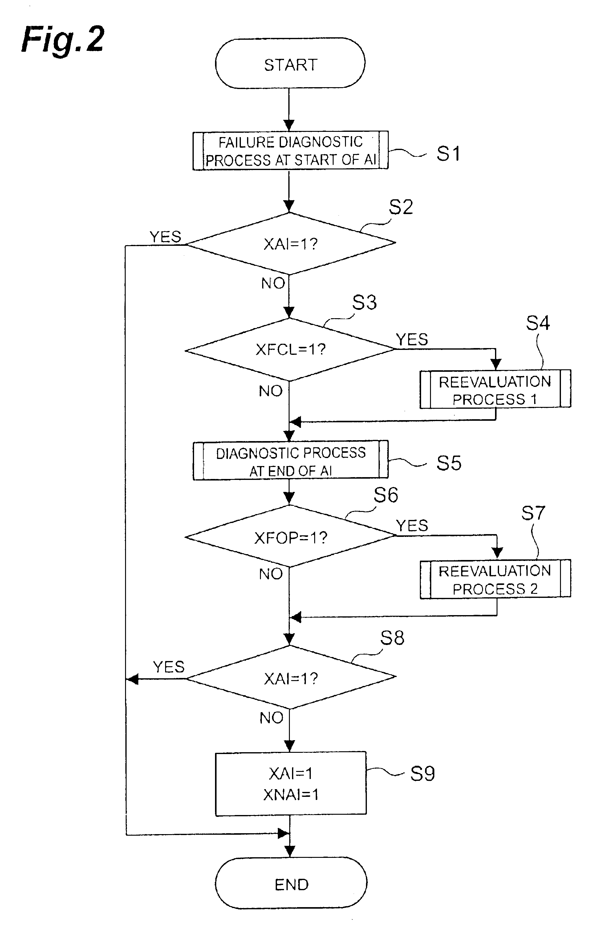
[0089]In the present embodiment, first step S601 is to carry out a failure diagnostic process. This failure diagnostic process is the same as the aforementioned failure diagnostic method and, specifically, it is executed based on the flowchart shown in FIG. 2. Subsequent step S602 is to check the value of the freezing failure flag FlagFS. This FlagFS is set by a routine presented in FIG. 15. Specifically, step S611 is to check the freezing open anomaly flag XFOP or the ...

third embodiment

[0105]The above described the examples in which the discharge process was carried out immediately after the failure determination, but it is also possible to employ a configuration of carrying out the discharge process after a lapse of a fixed time for standby since the failure determination, or a configuration of performing the failure determination at starting, stopping the engine with detection of a freezing anomaly, and thereafter carrying out the condensed water discharge control shown in FIG. 11. In these configurations, it is also preferable to adjust the time for purge according to the result of the failure determination. FIG. 20 is a flowchart of a method of adjusting the time for purge after the stop of the engine according to the result of the failure determination in the condensed water discharge control shown in FIG. 11. (This corresponds to the discharge control processing part in combinational control.)

[0106]The processing of steps S521 to S523 is the same as in the c...

fifth embodiment

[0113]It is also possible to perform the determination process after execution of the condensed water discharge. It is, however, noted that if the condensed water is frozen the condensed water discharge process immediately after starting of the engine will fail to discharge the condensed water, and it is thus preferable to discharge the condensed water after a warm-up. FIG. 23 is a flowchart showing combinational control. The present embodiment is configured to perform the condensed water discharge process between step S2 and step S3 in the flow of the failure diagnostic process shown in FIG. 2. At this point of time, the warm-up of the engine 2 is finished, so that the frozen condensed water should be melted with a high possibility. At this point ASV 13 is opened and the natural purge is carried out with AP 12 at a halt, or AP 12 is also actuated to effect the forced purge, thereby discharging the condensed water. After this, the reevaluation process or the determination process at...


PUM


Abstract

When the determination result of failure determination at a start of AI (auxiliary air injection=supply) is that there is a possibility of a closing anomaly due to freezing, a reevaluation process 1 being a reevaluation after a warm-up is performed. When the determination result of determination at an end of AI is that there is a possibility of an opening anomaly due to freezing, a reevaluation process 2 being a reevaluation after a warm-up is performed.

Description

BACKGROUND OF THE INVENTION[0001]1. Field of the Invention[0002]The present invention relates to auxiliary air supplying system for supplying auxiliary air to upstream of an exhaust emission control device in an exhaust system of an internal combustion engine, and to control methods and failure diagnostic methods thereof.[0003]2. Related Background Art[0004]As an exhaust emission control device of an internal combustion engine, there is a known system in which a catalytic converter is provided in the exhaust system to reduce CO, HC, NOx components, and others in the exhaust gas. Furthermore, there is the known technology of supplying auxiliary air through an auxiliary air inlet line provided with a control valve connected to an exhaust pipe, into the exhaust pipe to increase the oxygen content so as to induce secondary combustion of HC and CO in the exhaust gas, thereby facilitates cleaning-up the exhaust gas.[0005]In such auxiliary air supplying system, if something unusual occurs ...

Claims


Application Information

Patent Timeline
IPC IPC(8): F01N3/22F01N11/00
CPCF01N3/22F01N11/00F01N2550/14Y02T10/47Y02T10/22Y02T10/12Y02T10/40
Inventor HIROOKA, SHIGEMASAYOSHIOKA, MAMORU
Owner TOYOTA JIDOSHA KK
Why Eureka
Try Eureka