
Surface acoustic wave resonator with an interdigital transducer divided into regions having a different fixed pitch

a technology of interdigital transducer and surface acoustic wave, which is applied in the direction of generator/motor, kinetic-electric generator, device material selection, etc., can solve the problems of high q value equivalent, quartz-crystal oscillator is not obtained, and the frequency-temperature characteristics of the surface acoustic wave resonator can be enhanced

Active Publication Date: 2005-09-20
SEIKO EPSON CORP
View PDF10 Cites 8 Cited by
  • Summary
  • Abstract
  • Description
  • Claims
  • Application Information

AI Technical Summary

Benefits of technology

[0016]The present invention uses an R-ST substrate, to form a SAW resonator by using a quartz-crystal substrate having excellent frequency-temperature characteristics and having an excellent material Q value, realizes a small SAW resonator having a high Q value by using the above, and provides a SAW resonator and a voltage-controlled SAW oscillator, which are clock signal sources with low jitter and with low phase noise, using the above, in the high-speed wired communication market for Gigabit systems.
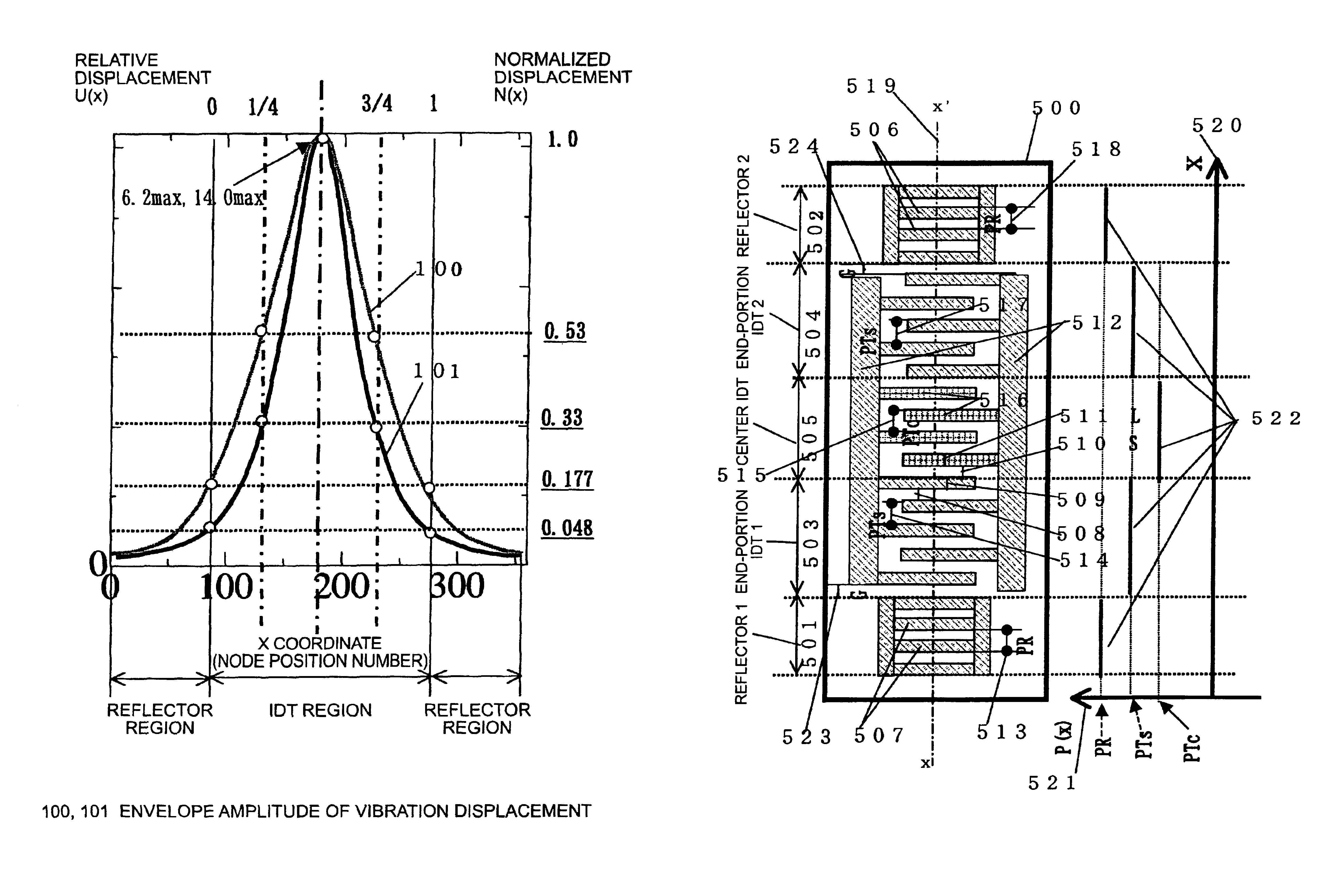
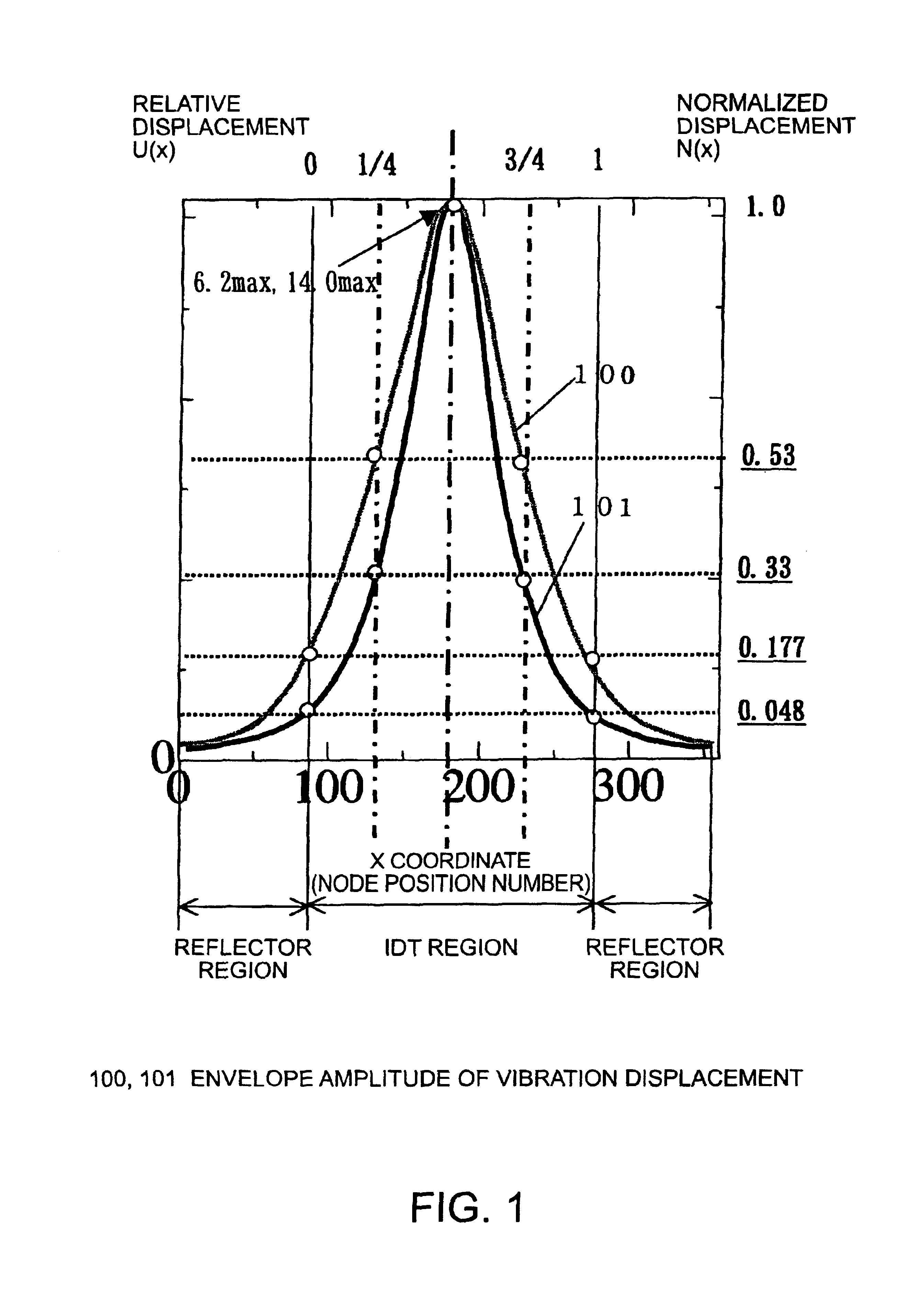
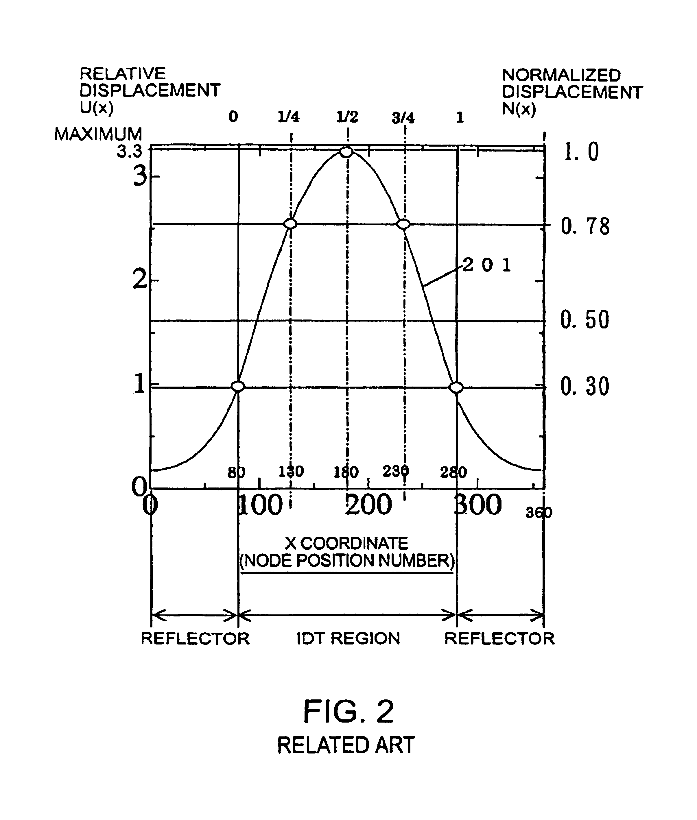
[0020]According to the above-described configuration, the displacement amplitude at positions at both ends of the IDT is decreased from 0.177 / 0.30=0.59 (approximately ½) to 0.048 / 0.30=0.16 (approximately ⅙) with respect to the related art standard-type displacement NO(x), and the degree of concentration of energy is increased. As a result, in a case where a reflector which is formed of the same number N and which causes the amplitude to be reduced to 1 / R is used, the surface acoustic wave which leaks outside the SAW resonator from the end portions of the reflector is reduced from approximately ½ to ⅙ in comparison with the related art case, and the Q value of the SAW resonator is theoretically squared conversion of the amplitude and can be increased from 4 times to 36 times. Furthermore, the equivalent series resistance R1 can be reduced from ¼ to 1 / 36 on the basis of the relation R1 =ωL1 / Q. If the Q value of the SAW resonator is to be maintained the same, the number of electrode conductors of the reflector can be reduced correspondingly and the dimensions can be decreased. In practice, since there are various causes for energy loss of the SAW resonator, there are advantages in that R1 becomes approximately ½, the Q value becomes double, and the device size is decreased by 20 to 30%.
[0027]With the above-described configuration, by applying the method of the present invention, the frequency-temperature characteristics of the surface acoustic wave resonator can be enhanced to approximately half (accuracy ±20 ppm) of the related art case (½) in a range of 0 to 70° C. without deteriorating the characteristics in comparison with the related art case, and thus there are advantages in that a quartz-crystal SAW resonator whose accuracy is higher than in the related art case, which is ±50ppm as a whole, can be realized.

Problems solved by technology

However, even if the above-described related art technology is used and the same configuration of the SAW resonator is taken, in the SAW resonator using the R-ST substrate, which is the subject of the present application, there are problems in that a high Q value equivalent to that of the related art technology and an appropriately low CI value (equivalent series resistance R1) when being used in a quartz-crystal oscillator are not obtained.
Therefore, at the same device size, the Q value is decreased, and the CI value is increased, and thus it becomes clear that miniaturization is difficult, which is a problem.

Method used


Image

  • Surface acoustic wave resonator with an interdigital transducer divided into regions having a different fixed pitch
  • Surface acoustic wave resonator with an interdigital transducer divided into regions having a different fixed pitch
  • Surface acoustic wave resonator with an interdigital transducer divided into regions having a different fixed pitch

Examples


Embodiment Construction

[0043]A one-port-type SAW resonator is formed in such a manner that, after the above-described ST-cut or rotated ST-cut plate (R-ST substrate) is cut out from a piezoelectric material made of quartz crystal (see FIG. 13) and the surface thereof is mirror-polished, an IDT is formed in which electrode fingers of many parallel conductors formed of, for example, aluminum metal, are arranged periodically in such a manner as to be at right angles to the phase propagation direction x of a Rayleigh-type or STW-type surface acoustic wave, and furthermore, a pair of reflectors are formed by periodically arranging many electrode conductors in strips on both sides of the IDT.

[0044]An exemplary embodiment of a one-port-type SAW resonator of the present invention is described below. First, to facilitate understanding, after the configuration of a specific exemplary embodiment is described with reference to FIG. 5, the form of the vibration displacement which specifies the basis of the present inv...


PUM


Abstract

In a substrate in which a reflection coefficient γ of a surface acoustic wave per electrode is small, the invention obtains a Q value or a CI value level, which is equivalent to or higher than that of a related art product, at a device size which is equivalent to the related art product which addresses the problem that the size of a surface acoustic wave resonator becomes larger. A surface acoustic wave resonator includes one interdigital transducer to excite a surface acoustic wave in a propagation direction x on a piezoelectric plate and a pair of reflectors arranged on both sides thereof in the propagation direction. The interdigital transducer is divided into three regions. The electrode fingers of the interdigital transducer of each region are formed at a fixed pitch which differs within 2%. The surface acoustic wave resonator possesses a single peak response. The form in which a vibration displacement envelope amplitude in the interdigital transducer region is normalized is a form which takes a maximum value 1 at the center position, which smoothly takes a value in a range of 0.33 to 0.53 at a position ¼ from both ends, and which smoothly takes a value in a range of 0.048 to 0.177 at positions at both ends.

Description

BACKGROUND OF THE INVENTION[0001]1. Field of Invention[0002]The present invention relates to a new type of so-called energy-trapping-type surface acoustic wave resonator (hereinafter “SAW resonator”), formed on a piezoelectric plate, such as a quartz crystal, in which vibration energy is greatly concentrated in the center of the resonator so as to increase the Q value and reduce the CI value by using a Rayleigh-type or STW (surface Transverse wave) type surface acoustic wave.[0003]2. Description of Related Art[0004]A related art SAW resonator, formed by using a quartz-crystal ST-cut substrate (an example of a piezoelectric plate) having piezoelectricity, can be used as an oscillation device of a quartz-crystal oscillator for data transmission in various high-speed network systems because the frequency-temperature characteristics thereof have a zero temperature coefficient and have excellent accuracy. This is advantageous in that a signal without jitter and whose phase noise is reduc...

Claims


Application Information

Patent Timeline
IPC IPC(8): H03H9/00H03H9/25H03H9/02H01L41/18H01L41/09H03H9/145
CPCH03H9/02551H03H9/25H03H9/14582
Inventor TAKAGI, MICHIAKIMAEDA, YOSHIOYAMAZAKI, TAKASHIIIZAWA, KEIGO
Owner SEIKO EPSON CORP
Learn More