Rake receiver for spread spectrum signal demodulation

Inactive Publication Date: 2005-09-20
III HLDG 1
View PDF7 Cites 10 Cited by
  • Summary
  • Abstract
  • Description
  • Claims
  • Application Information

AI Technical Summary

Benefits of technology

[0010]An objective of the present invention is to provide a system architecture for increasing the signal-to-noise ratio (SNR) of a spread spectrum signal. Another objective is to provide a system architecture for removing the interference from a spread spectrum signal, particularly the interference attributable to spread spectrum signals generated by other sources. Yet another objective is to provide a system architect

Problems solved by technology

In spread spectrum systems, all other spread spectrum signals contribute to background noise, or interference, relative to a selected spread spectrum signal.
Although “code” filters are used to isolate selected users, filter leakage results in the leakage of signals of other users into the signal of the selected user, thereby producing interference.
This leakage problem is particularly significant when the selected user is far away (and thus the user's signal is weak) and the interfering user is nearby (and thus the interfering user's signal is str

Method used


Image

  • Rake receiver for spread spectrum signal demodulation
  • Rake receiver for spread spectrum signal demodulation
  • Rake receiver for spread spectrum signal demodulation

Examples


Embodiment Construction

[0038]The present invention provides a software architecture and the underlying mathematical algorithms for demodulating / decoding communications signals containing interference noise. This invention is generally applicable to CDMA systems (and other spread spectrum systems), Frequency Division Multiple Access systems (FDMA) and Time Division Multiple Access systems (TDMA) and particularly for spread spectrum systems, such as CDMA. In spread spectrum systems, interference noise is typically due to a dense population of signals using the same intervals of the frequency spectrum, such as in high user density cellular phone applications, or such as in the intentional interference of radar or communication signals by nearby jammers.

[0039]Single Antenna Systems

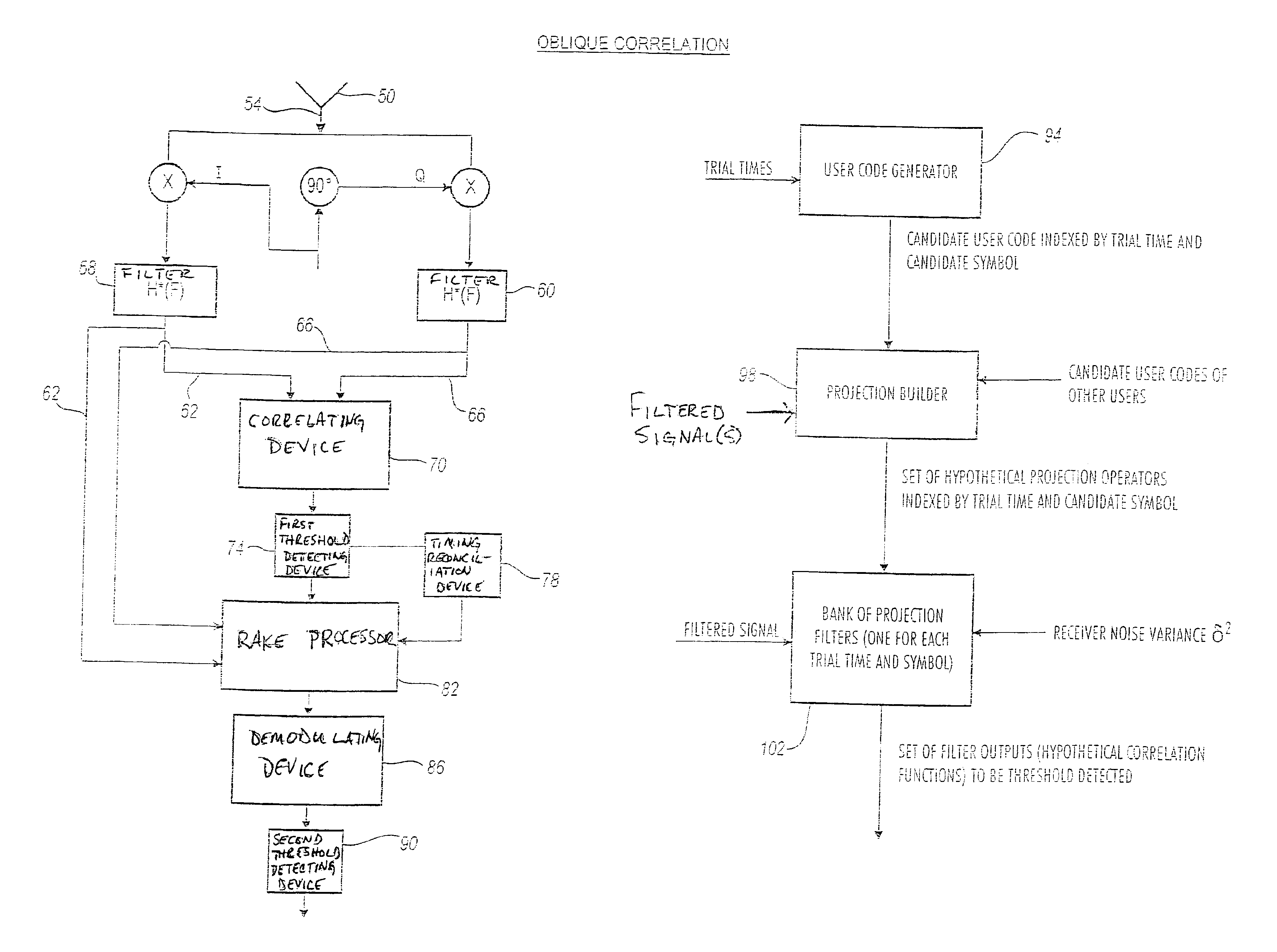
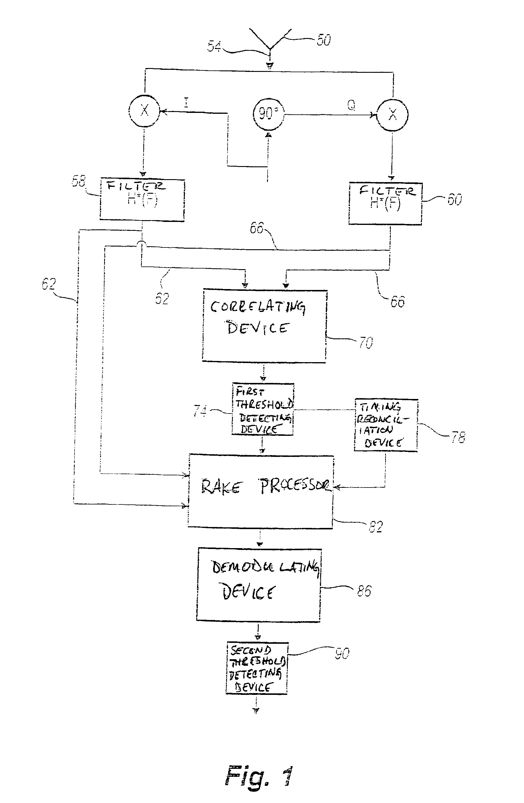
[0040]An overview of the current architecture for detecting signals from an ith user in a CDMA system is illustrated in FIG. 1. The architecture employs a single antenna for receiving CDMA signals. The system includes the antenna 50...


PUM


Abstract

The architecture of the present invention is premised upon an algorithm involving integration of oblique correlators and RAKE filtering to null interference from other spread spectrum signals. The oblique correlator is based on the non-orthogonal projections that are optimum for nulling structured signals such as spread spectrum signals. In one configuration, space spanned by a first signal associated with a first emitter is orthogonal to an interference space associated with one or more signals of one or more other emitters. RAKE filtering is used to rapidly steer the beam of the multi-antenna system and to mitigate the effects of multipath.

Description

CROSS REFERENCE TO RELATED APPLICATIONS[0001]The present application is a continuation-in-part of U.S. Patent Application entitled “Rake Receiver For Spread Spectrum Signal Demodulation”, having Ser. No. 09 / 612,602, filed Jul. 7, 2000 now U.S. Pat. No. 6,430,216, which is a continuation of U.S. Patent Application entitled “Rake Receiver For Spread Spectrum Signal Demodulation”, having Ser. No. 08 / 916,884, filed Aug. 22, 1997 now abandoned, which claims priority under 35 U.S.C. §119(e) from U.S. Provisional Application entitled “PHASED-RAKE RECEIVER FOR SIGNAL DEMODULATION”, having Ser. No. 60 / 024,525 and filed Aug. 23, 1996, and is a continuation-in-part of U.S. patent application entitled “Method and Apparatus for Acquiring Wide-Band Pseudorandom Noise Encoded Waveforms” having Ser. No. 09 / 137,383, filed Aug. 20, 1998 now U.S. Pat. No. 6,252,535, which claims priority under 35 U.S.C. §119(e) from U.S. Provisional Applications entitled “Method and Apparatus for Acquiring Wide-Band P...

Claims


Application Information

Patent Timeline
IPC IPC(8): H01Q3/26H04B7/10H04B7/02H03M1/12H04B1/707H04B7/08G01S1/00G01S1/04G01S7/02G01S7/285H04B1/10H04B1/709H04B1/7107
CPCH01Q3/2605H04B1/7107H04B7/0845H04B7/0891H04B7/10G01S1/045G01S7/021G01S7/285H04B1/1081H04B1/709
Inventor KOBER, WOLFGANGTHOMAS, JOHN K.VIS, MARVIN L.
Owner III HLDG 1
Why Eureka
Try Eureka