Cutting roller for a continuously operating surface miner

a technology of cutting roller and surface miner, which is applied in the direction of cutting machines, open-pit mining, soil-shifting machines/dredgers, etc., can solve the problems of reduced mining output, increased energy consumption and wear of free-cutting rollers, and increased production losses, so as to achieve low specific energy consumption, low dust emission, and high strength

Inactive Publication Date: 2005-09-27
MAN TAKRAF FORDERTECHN
View PDF8 Cites 4 Cited by
  • Summary
  • Abstract
  • Description
  • Claims
  • Application Information

AI Technical Summary

Benefits of technology

[0006]The basic object of the present invention is to develop a cutting roller for a continuously operating surface miner for mining mineral raw materials possessing solid and abrasive properties, comprising a roller basic body, which is substantially cylindrical and is provided with a drive and is fastened to the surface miner by means of supports. The roller jacket is equipped with mini-disk bits arranged in rolling paths, and conveying screws, which have opposite pitches and extend from the two edges of the roller to the middle of the roller, are arranged, and two roller halves, which are symmetrical to one another, are thus formed, and the mineral raw materials are mined from the soil by the cutting roller in blocks, wherein the larger, middle area is called the mining front, which is joined on both sides by the edge areas. This guarantees, on the one hand, the mining of earth materials of high strength in general with a relatively low specific energy consumption according to the cutting method and is thus suitable for use in surface miners, rotary cutters for road construction or even breakers and, on the other hand, combines in itself the advantages, such as won minerals in the form of coarse lumps because of the splitting breaking operation, low dust emission and high stability due to rolling contact with the rock in place, good service life and mining output due to the reduction of the loss of time for replacing bits (the wear on the disk bits is reduced by a factor of 10) and the avoidance of a lateral accumulation of material having escaped to the outside. The mining member shall be equipped with a simple type of bit and guarantee the generally difficult mining operation in the edge area in a stable manner and shall cleanly clear the separated material.
[0007]This object is accomplished with a cutting roller that with a repeatedly blocked separation operation. Screw turns (double helix arrangement) with opposite pitches arranged on the circumference are equipped with mini-disk bits on the roller halves of equal size of the jacket of the cutting roller, and the separation as well as the combined radial and transverse conveying of the separated material is thus guaranteed simultaneously. The driving wedge flanks of the mini-disk bits of one roller half are directed opposite those of the second half of the roller, and the side forces generated are thus eliminated. The screw turns at the edge of each roller half and the basic body of the cutting roller are designed such that the virtual path diameters formed by the mini-disk bits form a truncated cone, and as a result, the surface of the track level forms a trough-shaped profile at right angles to the direction of travel after the separation operation. As a result, less earth material is removed in the area of the frustum of the cone. Lower mining resistances develop there. Furthermore, a smaller volume of separated material, which must be conveyed by the transverse conveying to the middle of the roller, is formed in the edge areas of the cutting roller. A dimension of at least ¼ of the mining height shall be maintained for the width of the frusta at the edge of the cutting roller, because the height of the remaining trough side residues is smaller in the case of this geometry than in the middle of the roller. The two trough side residues located next to each other from two mining directions form together an elevation whose profile converges in an apex. This elevation is removed without problems during the mining of the subjacent block due to the rise, larger deposits are removed with the middle part of the cutting roller, the wall area, and thus it does not have an adverse effect on the overall mining technology. No lateral accumulations are formed during the mining operation due to the laterally directed breaking operation under the wedge flanks of the mini-disk bits and the rolling contact as well as the smaller volume removed in the edge areas and the improved pick-up capacity of the scraper blade in the trough-shaped track level. The mining output increases and the energy consumption is reduced as a result.
[0008]To simplify the design of the cutting roller with the double helix arrangement of the conveying screws and the mini-disk bits and to minimize the manufacturing costs, the conveying screws are directed from the edge toward the middle of the roller on each of the two roller halves. Since the separation takes place with a higher mining resistance in the edge area due to the edge effect, at least a double density of disk bits is installed on the edge area in a rolling path by means of shorter additional conveying screws. Due to the double density of mini-disk bits, the penetration in the edge area of the cutting roller is only half the penetration in the area of the middle mining front, the wall area. It is therefore possible to increase the height of the conveying screws in the truncated cone-shaped edge areas by this dimension of smaller penetration of these mini-disk bits arranged in the edge area, and the quality of clearing of the track level and the energy transmission of the mini-disk bits are substantially improved, and a lower specific energy consumption is thus obtained. It is advantageous that the entire cutting roller can be equipped with one type of bits.

Problems solved by technology

This free-cutting is associated with a considerably higher energy consumption and wear and calls for special equipment for the mining member with tools in the edge area compared with the rest of the larger middle area.
These lead to a reduction in the mining output and require the use of an additional clearing technique.
As a result, additional losses of output must be accepted.
Other drawbacks of such a roller-shaped mining member equipped with round-shaft bits are that high energy losses and intense wear occur on the bits due to the sliding contact of the bits in the case of abrasive earth materials.
The specific energy consumption also increases enormously if the compressive strength of the deposits of mineral raw materials is higher than 60 MPa and makes the use of surface miners uneconomical.
Another drawback is that pulverized rocks generate increased dust emission during the mining operation.
Strong tear-out forces, which lead to the formation of large chunks, are generated on the bits in case of the overshot mining method.
This is a considerable obstacle for the entire mechanical mining operation and may lead to a reduction of output, or an additional intermediate breaker becomes necessary.
Due to its narrow design and because the separated material is conveyed on one side only, as well as due to the arrangement of the disk bits after the free cut (as a consequence of which the bit density is relatively high and there are strong pressing forces), these cutter loaders are not suitable for economical use during the mining of hard and thin layers with surface miners because of the insufficient mining output.
In addition, the use of two types of bits with closing rings is technologically and economically unfavorable.
This compressive strain leads to the tensile and shear load on the material under and to the side of the track of the disks.
The drawbacks of a surface miner based on this concept is that due to the frontal contact of all disk bits with the rock surface with a track distance of 200 mm and rolling over only once, practically no artificial flank can be formed, because a great arc length can be expected in case of a disk diameter of 350-430 mm, which requires an enormously high pressing force for sufficient penetration.
Furthermore, the use of two mining members leads to a widening of the distance between the caterpillars and consequently to unfavorable conditions for manoeuvering at the end of the face.

Method used


Image

  • Cutting roller for a continuously operating surface miner
  • Cutting roller for a continuously operating surface miner
  • Cutting roller for a continuously operating surface miner

Examples


Embodiment Construction

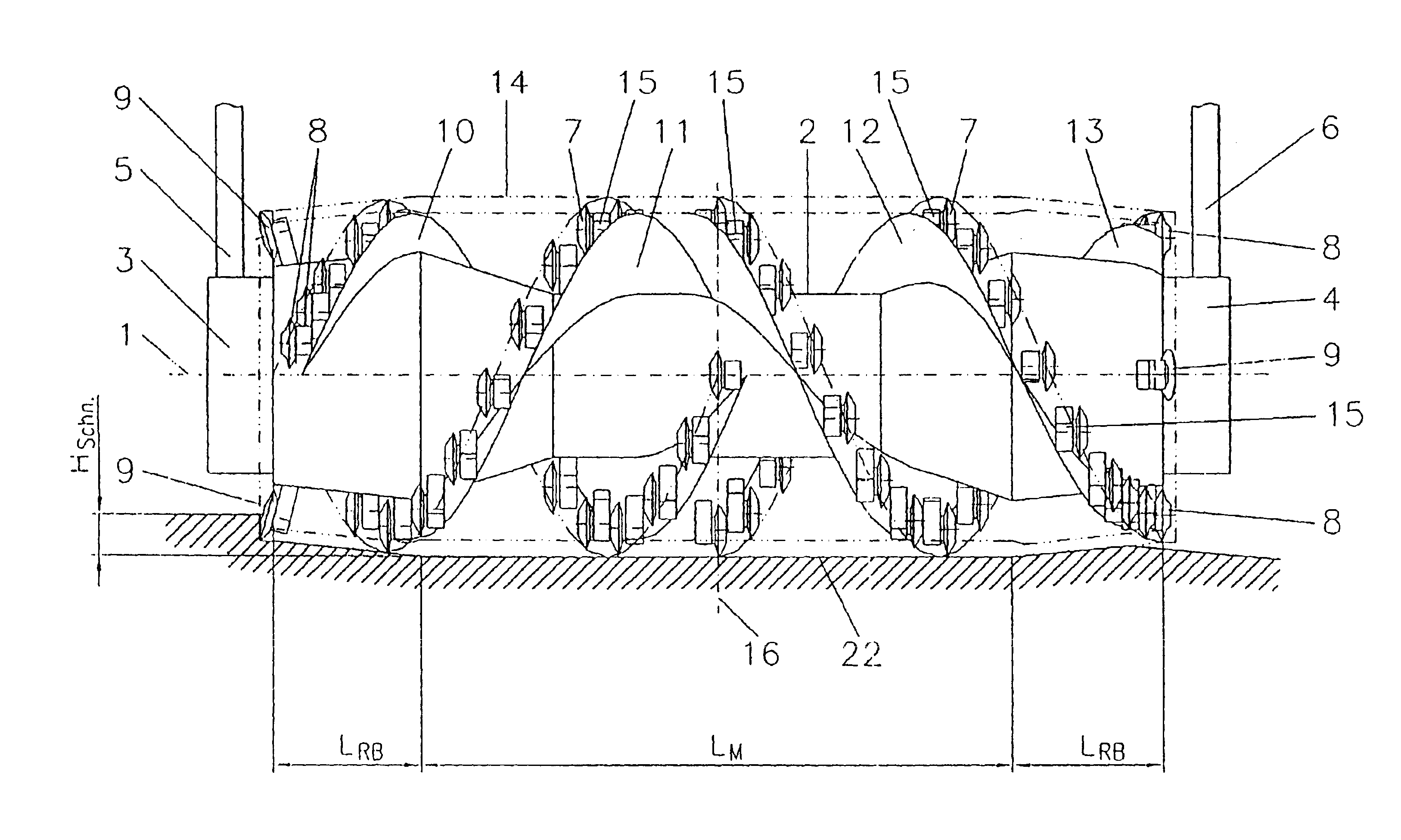
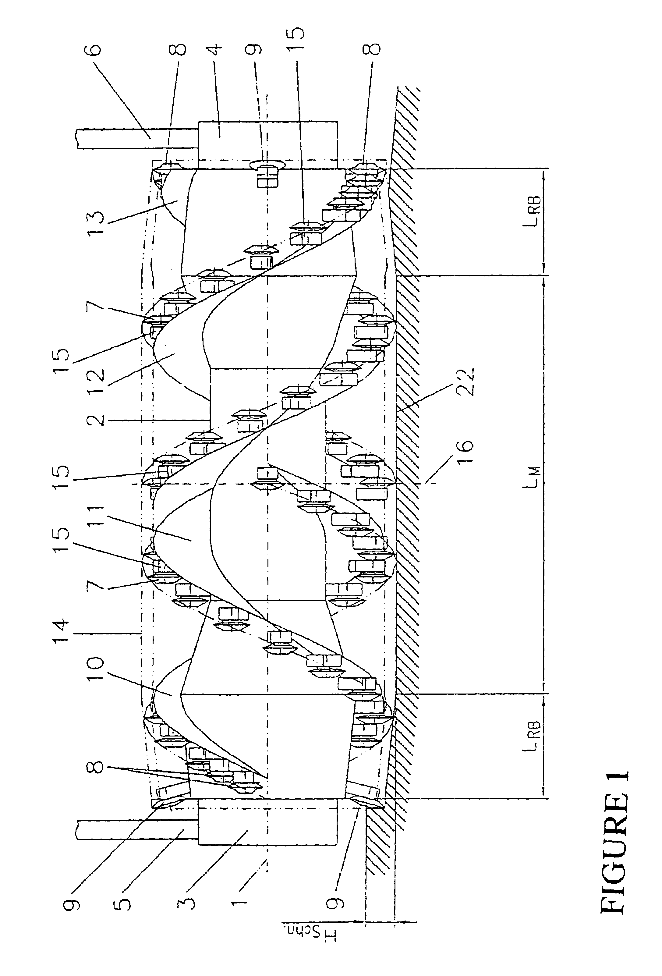
[0015]Referring to the drawings in particular, the cutting roller shown in FIG. 1 is the mining member for a surface miner for mining earth materials of high strength such as hard coal, ores and other mineral raw materials with high compressive strengths between 50 MPa and 140 MPa. Such a continuously operating surface miner, which is, however, not designed with its mining member for mineral raw materials of such a high compressive strength, is known from, e.g., Patent No. DE 199 41 799 A1. The cutting roller is arranged with its axis of rotation 1 in the horizontal position in front of the device in the mining direction. However, this is not a requirement. It may also be arranged between the front and rear chassis or at the end of the device.

[0016]The cutting roller comprises a roller jacket 2, in which a drive 3, 4 each is accommodated on both sides. The cutting roller is fastened to the surface miner by supports 5, 6, which are arranged at the frame of the device on both sides an...


PUM


Abstract

A mining member designed as a cutting roller for a continuously operating surface miner for mining mineral raw materials of high strength. The roller body is equipped for this purpose with mini-disk bits of identical design. Since different conditions occur over the entire width of the roller during the separation of the material from the soil, the roller body is designed correspondingly, and the arrangement of the mini-disk bits is adapted to these conditions. The mini-disk bits in the edge areas are placed at a greater density than are the mini-disk bits (7) in the middle area. In addition, mini-disk bits are directed obliquely toward the outside as free-cutting bits at the two outer edges of the cutting roller. The height of the mini-disk bits is selected to be such that their individual virtual rolling paths together form a virtual cutting roller body, which comprises a middle cylinder, which is joined on both sides by outwardly tapering frusta. This solution is associated with the advantages that more mini-disk bits are available per unit area in the critical edge areas for separating the material and for cutting the roller free, and the cutting height HSchn is smaller there.

Description

FIELD OF THE INVENTION[0001]The present invention pertains to a mining member designed as a cutting roller for a continuously operating surface miner. Such a cutting roller is especially suitable for use for mining high-strength mineral raw materials such as hard coal, ores, etc., with compressive strengths between 50 and 140 MPa by means of surface miners. However, it may also be used in rotary cutters for road construction and breakers.BACKGROUND OF THE INVENTION[0002]When a surface miner is used as surface mining equipment with a roller-shaped mining member (a frontal mining portion that is attached via a support to a caterpillar) rotatable around its horizontal axis, the mining operation is carried out, in general, according to the so-called cutting operation. According to its basic concept, the mining member of such a device, as is known from, e.g., the patent DE 199 41 801 C2, has a roller width that is greater by a factor of 5 to 8 (as a result of which it can also be defined...

Claims


Application Information

Patent Timeline
Patent Type & Authority Patents(United States)
IPC IPC(8): E02F3/24E21C25/10E21C25/00E21C25/16E02F3/18E21C47/02
CPCE02F3/241E21C25/10E21C25/16
Inventor EHLER, ALEXANDERKUNZE, GUNTERSCHRADER, VOLKMARPETACK, BURKHARDPOTENBERG, KLAUS
Owner MAN TAKRAF FORDERTECHN
Why Eureka
Try Eureka