
Method of supplying liquid gas to an internal combustion engine, a fuel supply system and a fuel supply aggregate

a technology of liquid gas supply and internal combustion engine, which is applied in the direction of fuel systems, conveying machines, mechanical equipment, etc., can solve the problems of significant technical expenditure, increase in system pressure, and vapor bubbles in the liquid gas supply line, so as to reduce the loss of throttle and increase the fuel injection

Inactive Publication Date: 2005-10-11
PAUL UITENBROEK HLDG BV
View PDF7 Cites 9 Cited by
  • Summary
  • Abstract
  • Description
  • Claims
  • Application Information

AI Technical Summary

Benefits of technology

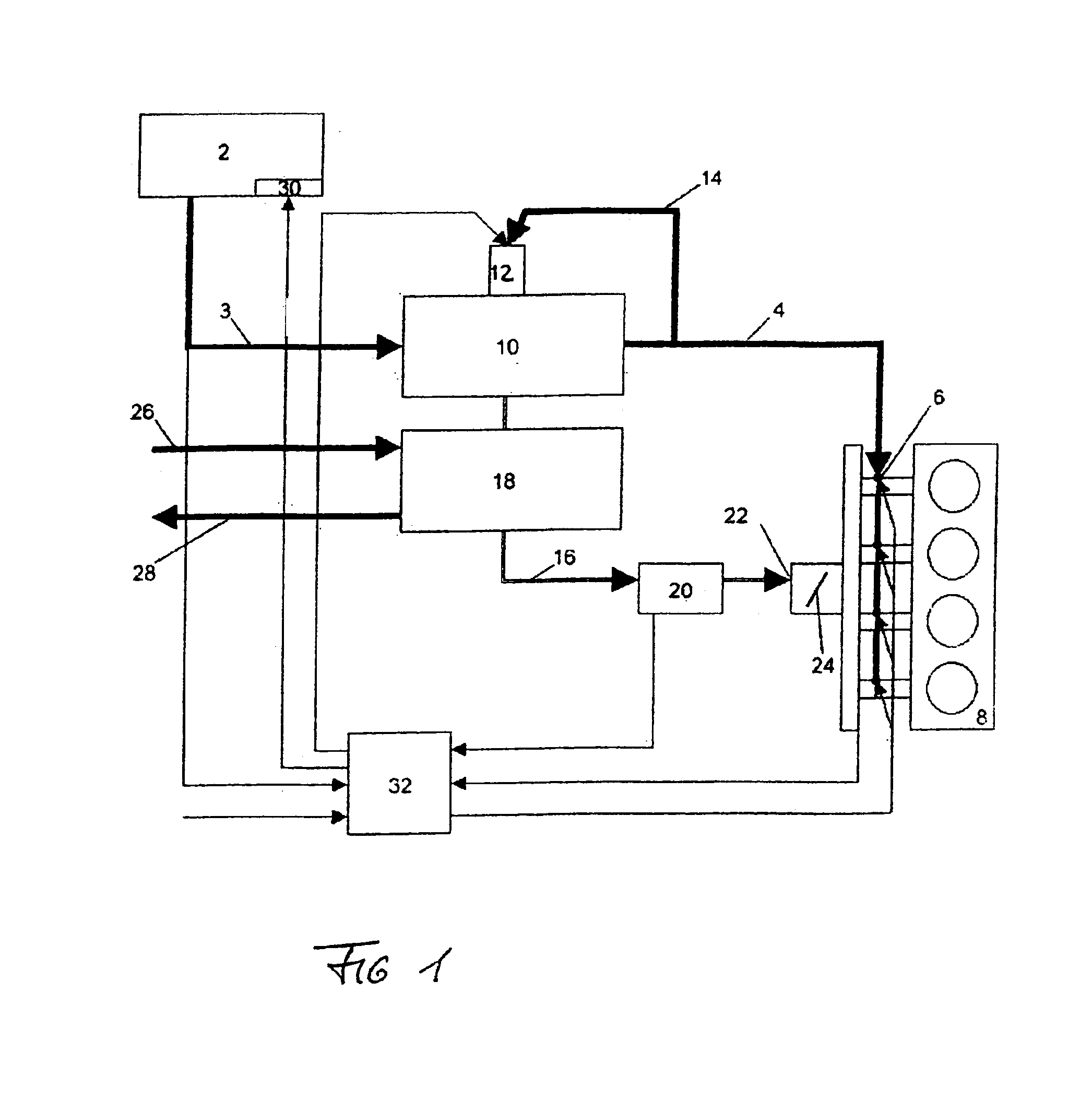
[0010]Consequently, with the inventive method the liquid gas stream that is to be metered is divided, in an electronically controlled manner, into a gaseous or vaporous partial stream and a liquid partial stream. In this connection, the enthalpy of vaporization required for the generation of the gaseous partial stream is withdrawn from the liquid partial stream. The temperature reduction connected therewith prevents vapor bubbles from forming in the liquid gas stream, and thus also prevents the aforementioned metering problems as a consequence of a two-phase flow. The electronically regulated division or splitting of the fuel stream furthermore enables, at partial load or throttle operation of the engine, a greater percentage (up to 100%) of gaseous supply to the engine, and at full throttle a greater percentage of liquid phase supply. This reduces the throttle losses at lower loads and increases the fuel injection at full throttle.
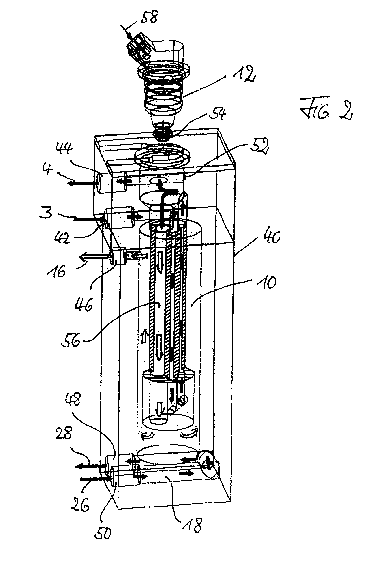
[0014]The fuel supply aggregate for the fuel supply system includes a housing having a seat for the mounting of the expansion device, with the housing also being provided with the cooling heat exchanger, the heating heat exchanger as well as connections for the supply of liquid gas, the outlet for cold liquid gas, the outlet for gaseous liquid gas, the inlet for cooling water and the outlet for cooling water. By means of this fuel supply aggregate, it is possible to apply the fuel supply system of the present application in an economical manner to any engine that is operated with liquid gas.

Problems solved by technology

With the supply of such liquid gases to the mixture forming systems of internal combustion engines, which is generally effected via precisely controlled injection valves, there occurs the problem that vapor bubbles form in the liquid gas supply line that occur, for example, when, upon opening of the injection valve, the system pressure drops below the pressure at which the liquid gas is liquid at the prevailing temperature.
Connected with an increase in the system pressure is a significant technical expenditure for the pumps, since liquid gas has poor lubrication properties.
In addition, the fuel system must have a return line, since with low fuel throughputs the pressure increase effected by the pumps is not adequate to compensate for the tendency to form vapor bubbles caused by heating.
At partial load, the indicated characteristic has a drawback that due to the increased mixture density and / or the lower intake temperature a greater throttling must be effected, which leads to intake losses.

Method used


Image

  • Method of supplying liquid gas to an internal combustion engine, a fuel supply system and a fuel supply aggregate
  • Method of supplying liquid gas to an internal combustion engine, a fuel supply system and a fuel supply aggregate
  • Method of supplying liquid gas to an internal combustion engine, a fuel supply system and a fuel supply aggregate

Examples


first embodiment

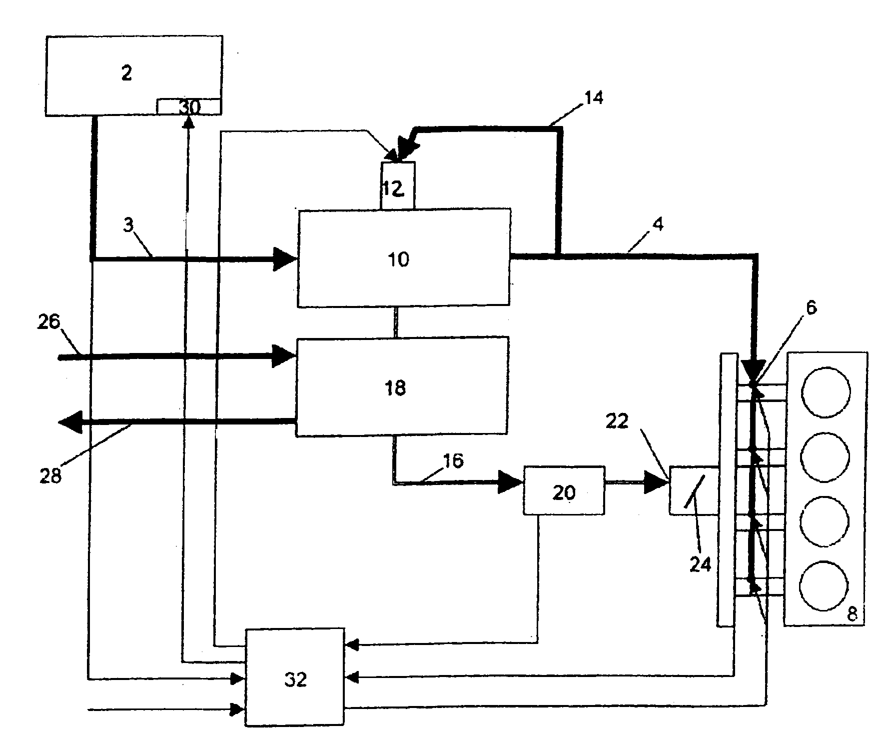
[0023]Pursuant to the first embodiment, the expansion device 12 is formed by a fixed-cycle or timing valve that is controlled by the control unit 32 in such a way that a gas pressure is established in the working tank 20 that is a function of the operating conditions of the internal combustion engine. In this case, the vapor feed device 22 is an admixing valve having a constant opening, so that the quantity of the gas passing into the internal combustion engine results to a large extent from the pressure in the working tank 20.

second embodiment

[0024]Pursuant to the second embodiment, the expansion device 12 is formed by a pressure-regulating valve, for example a simple diaphragm valve, so that a constant vapor or gas pressure is established in the working tank 20. The metering of the gas supply to the internal combustion engine is effected via the vapor feed device 22, which is embodied as an electrically controllable valve, the effective valve opening area of which is controlled by the control unit 32.

[0025]It is to be understood that combined controls could also be utilized, where not only the pressure in the working tank 20 can be varied via the expansion device (fixed-cycle or a proportionally controllable valve) that is controlled by the control unit 32, but also the effective flow-through area of the vapor feed device 22 can be varied by the control unit 32. For example, the expansion device 12 can be embodied as an electrically controllable pressure-regulating unit. The vapor feed device 22 can also be embodied as ...


PUM


Abstract

A method and apparatus are provided for supplying liquid gas as fuel to an internal combustion engine. From the liquid gas stream that is supplied to at least one liquid gas injection valve of the internal combustion engine, a portion is branched off and expanded. The liquid gas stream supplied to the internal combustion engine is cooled with coldness that results during the expansion, thus ensuring that the liquid gas stream supplied to the liquid gas injection valve is at least substantially liquid. The expanded liquid gas is supplied in a vaporous state to the internal combustion engine.

Description

BACKGROUND OF THE INVENTION[0001]The present invention relates to a method of supplying liquid gas as fuel to an internal combustion engine. The invention furthermore relates to a fuel supply system for an internal combustion engine that is operated with liquid gas, and also to a fuel supply aggregate for such a fuel supply system.[0002]Internal combustion engines that operate with liquid gas as fuel are finding increasing application, especially due to the improved environmental compatibility in contrast to conventional, liquid fossil fuels. In the following, the term liquid gas refers to liquefied gas, for example liquid natural gas or liquid petroleum gas, which are primarily gases based on hydrocarbons that are liquid at greater than atmospheric pressure and / or at less than the normal ambient temperature.[0003]With the supply of such liquid gases to the mixture forming systems of internal combustion engines, which is generally effected via precisely controlled injection valves, ...

Claims


Application Information

Patent Timeline
Patent Type & Authority Patents(United States)
IPC IPC(8): F02B43/12F02B43/00
CPCF02B43/12Y02T10/16Y02T10/32Y02T10/12Y02T10/30B02C17/16B09B3/00B65G47/18B65G2812/0511Y02W30/52
Inventor UITENBROEK, PAUL
Owner PAUL UITENBROEK HLDG BV
Learn More