High strength steel weld having improved resistance to cold cracking and a welding method

a technology of high strength steel which is applied in the direction of heat treatment equipment, soldering equipment, furnaces, etc., can solve the problems of increasing the susceptibility of the weld metal to cold cracking, reducing the toughness of the weld metal, and reducing the efficiency of field (on-site) welding, so as to improve the low temperature toughness and resistance to cold cracking. , the effect of high tensile strength

Inactive Publication Date: 2005-10-11
NIPPON STEEL CORP
View PDF4 Cites 22 Cited by
  • Summary
  • Abstract
  • Description
  • Claims
  • Application Information

AI Technical Summary

Benefits of technology

[0011]The present invention provides a high strength steel weld having a high tensile strength of at least 750 MPa and improved low temperature toughness and resistance to cold cracking in, for example, a high strength steel pipe which is manufactured by the submerged arc welding method and which has a high tensile strength of at least 750 MPa. The present invention also provides a welding method which can form such a weld in a reliable manner.

Problems solved by technology

However, if the wall thickness of the pipe is increased, the efficiency of field (on-site) welding decreases, and it may become necessary to strengthen the foundation supporting the pipeline due to the increased weight of the pipe.
However, if a weld metal contains a large amount of alloying elements, an increased amount of hydrogen is taken up into the weld metal during welding, thereby significantly increasing the susceptibility of the weld metal to cold cracking.
However, due to the increased amount of oxygen in the weld metal, not only does the toughness of the weld metal decrease, but it also becomes easy for defects such as slag inclusions and pinholes to occur in the weld metal, leading to a decrease in weld quality.
In the examples of that patent, the temperature at the completion of cooling is in the range of 500-300° C. In that method, the welding techniques which can be employed are restricted, and hence it cannot be applied to steel pipe, for example.

Method used


Image

  • High strength steel weld having improved resistance to cold cracking and a welding method
  • High strength steel weld having improved resistance to cold cracking and a welding method

Examples


examples

[0064]The following examples are included merely to illustrate the present invention by taking the case in which the present invention is applied to a welded steel pipe for a pipeline or similar structure.

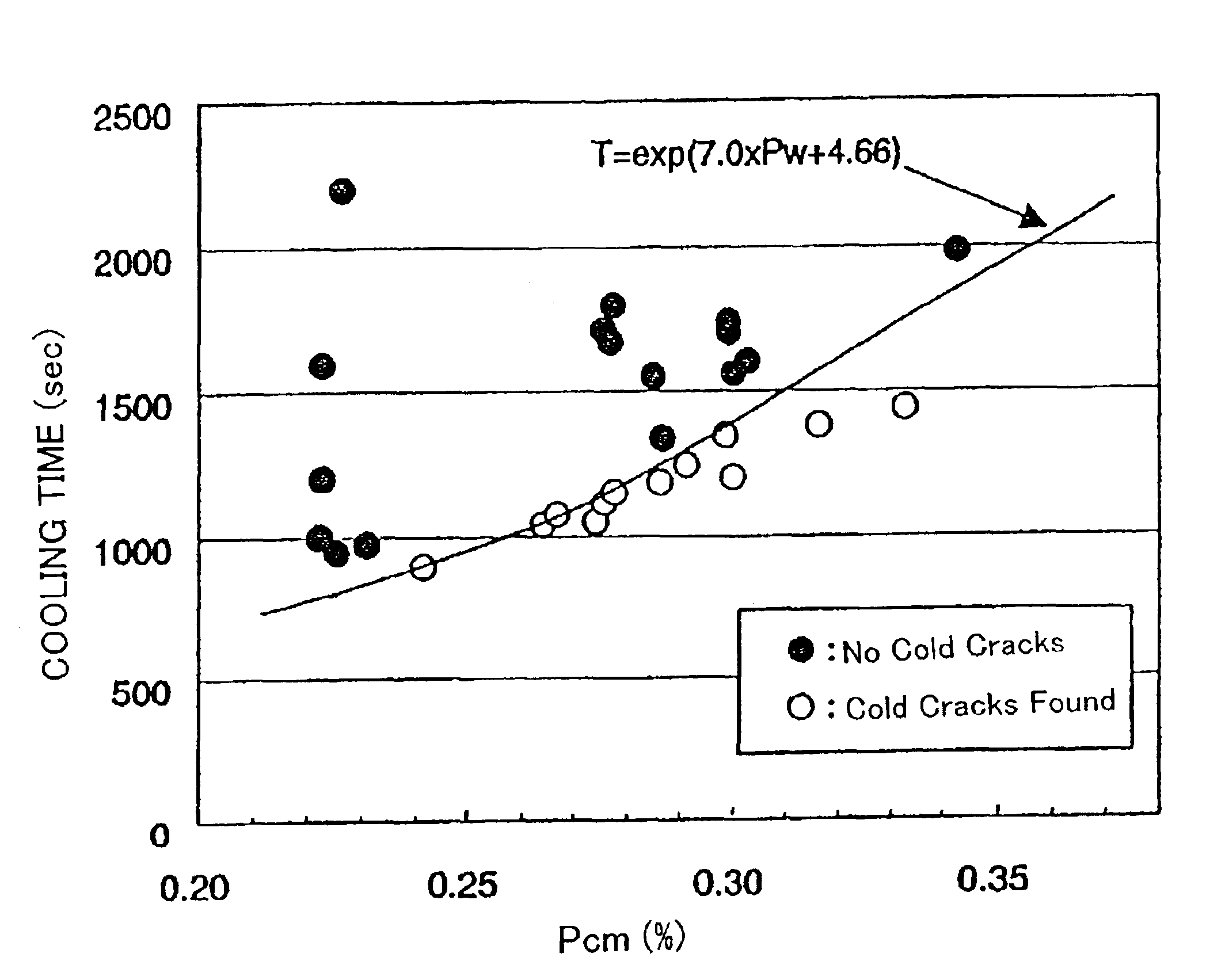
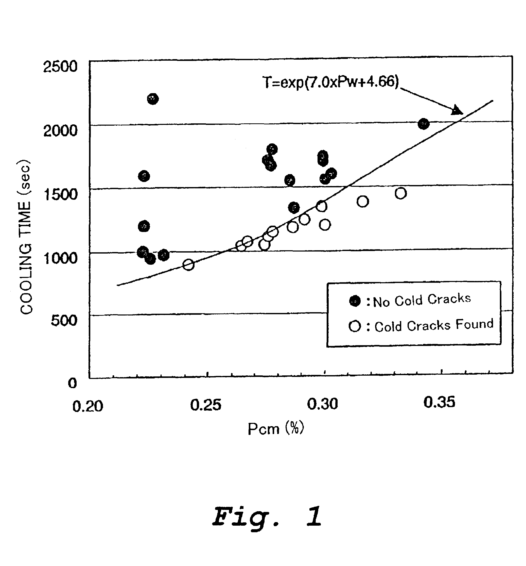
[0065]Welded steel pipe having a wall thickness of from 12 mm to 24 mm [outer diameter: from 500 mm (20 inches) to 1500 mm (60 inches)] was manufactured using UOE steel pipe manufacturing equipment from steel strip having various chemical compositions obtained by continuous casting and hot rolling. Welding was carried out by the submerged arc welding (SAW) method using various fluxes and welding wires. The time for the weld metal to cool to 100° C. after welding was measured by measuring the temperature of the weld metal using a non-contacting type thermometer. The cooling time T was adjusted by preheating prior to welding or by heat insulating after preheating.

[0066]The amount of hydrogen in the weld metal immediately after welding (HD: ml / 100 g) was measured by an experiment usin...


PUM

PropertyMeasurementUnit
tensile strengthaaaaaaaaaa

Abstract

A welding method includes performing welding to form a weld metal consisting essentially of, in mass %,

C: 0.01-0.15%,
Si: 0.02-0.6%,
Mn: 0.6-3.0%,
Al: 0.004-0.08%,
Ti: 0.003-0.03%,
B: at most 0.005%,
Cu: 0-1.2%,
Ni: 0-3%,
Cr: 0-1.2%,
Mo: 0-2%,
V: 0-0.05%,
Nb: 0-0.05%,
and a remainder of Fe and unavoidable impurities. The amounts of impurities are P: at most 0.03%, S: at most 0.03%, N: at most 0.01%, Ca or Mg: at most 0.005%. The value of Pcm expressed by the following Equation (3) is in the range of 0.23-0.35%, and the time T until the weld metal is cooled to 100° C. after welding satisfies the following Equation (1):
T(seconds)≧exp(7.0×Pw+4.66)  Equation (1)
Pw=Pcm+HD/60  Equation (2)
Pcm(mass %)=C+Si/30+Mn/20+Cu/20+Ni/60+Cr/20+Mo/15+V/10+5B  Equation (3)
    • HD [ml/100 g]: amount of hydrogen in the weld metal immediately after welding.

Description

BACKGROUND OF THE INVENTION[0001]1. Technical Field[0002]This invention relates to a high strength steel weld having a tensile strength (TS) of at least 750 MPa along with improved low temperature toughness and improved resistance to cold cracking, and a welding method capable of forming such a weld. A steel weld and a welding method according to the present invention are suitable for use in high strength steel structures such as welded steel pipes for pipelines and other uses, offshore structures, pressure vessels, tanks, and ship hulls.[0003]2. Related Art[0004]In a pipeline for transporting natural gas, crude oil, or similar material over long distances, if the operating pressure is increased, the transport efficiency of the pipeline is improved and transport costs are decreased. In order to increase the operating pressure, it is necessary to either increase the wall thickness of the pipe forming the pipeline or increase the strength of the material of which the pipe is formed. H...

Claims


Application Information

Patent Timeline
Patent Type & Authority Patents(United States)
IPC IPC(8): C22C38/58C22C38/44C22C38/48C22C38/42C22C38/54C22C38/46C21D1/84C21D9/50B23K9/18
CPCB23K9/18C22C38/42C22C38/44C22C38/46C22C38/48C22C38/54C22C38/58C21D1/84C21D9/505
Inventor IKEDA, TOMOAKIYAMAMOTO, AKIOYAMAUCHI, SHIGEMICHITAKAHASHI, NOBUAKIHAMADA, MASAHIKO
Owner NIPPON STEEL CORP
Why Eureka
Try Eureka