High-purity fluorine gas, production and use thereof, and method for analyzing trace impurities in high-purity fluorine gas

a high-purity fluorine gas and trace impurity technology, which is applied in the field of high-purity fluorine gas, the production and use thereof, and the method of analyzing trace impurities in high-purity fluorine gas, can solve the problems of difficult handling of fluorine gas, analysis methods that cannot be optimal, and scarcely traded fluorine gas on a commercial basis. achieve the effect of reducing the pressure inside the container

Inactive Publication Date: 2005-10-18
SHOWA DENKO KK
View PDF14 Cites 16 Cited by
  • Summary
  • Abstract
  • Description
  • Claims
  • Application Information

AI Technical Summary

Benefits of technology

[0013]A further object of the present invention is to provide a method for analyzing trace impurities in a high-purity fluorine gas, where the contamination from a metal material coming into contact with a fluorine gas or from fluorine gas-removing and separating agent is prevented.

Problems solved by technology

A fluorine gas is a combustion-supporting gas having strong oxidative property and also has strong toxicity and corrosiveness and therefore, in Japan, fluorine gas is scarcely traded on a commercial base except in a special case.
However, these analysis methods cannot be an optimal method as the analysis method for a high-purity fluorine gas, containing trace impurities in a concentration of hundreds of vol. ppm or less, even though such high-purity fluorine gas is an important key technology for the development of semiconductor industry.
Fluorine gas is difficult to handle because it is highly reactive (oxidative) and in turn highly corrosive.
Therefore, fluorine gas cannot be introduced directly into an analyzer.
Even in the case of gas chromatography which is effective for analyzing the composition of gas components, almost no method has been heretofore known for the analysis of trace impurities in a fluorine gas, because, for example, there is no appropriate separation column where fluorine gas can be directly introduced.
This phenomenon cannot be overcome merely by a baking treatment and, due to the increase of O2 background, these methods cannot be accurate as a quantitative analysis method of trace oxygen gas in a fluorine gas.
In the case of analyzing trace impurities, the dissolution and absorption of impurities in the aqueous solution raise a problem and in some cases, the quantitative analysis cannot be exactly performed.
However, the problem of impurities, particularly oxygen, generated in the previous stage from the inner surface of equipment or material coming into contact with the fluorine gas or from the fluorine gas-removing and separating agent still remains unsolved.
However, other than these impurities, the fluorine gas contains impurities such as HF, SiF4 and other metal fluorides and unless these impurities can be analyzed, the method cannot be said to attain a function as an analysis method of trace impurities.

Method used


Image

  • High-purity fluorine gas, production and use thereof, and method for analyzing trace impurities in high-purity fluorine gas
  • High-purity fluorine gas, production and use thereof, and method for analyzing trace impurities in high-purity fluorine gas
  • High-purity fluorine gas, production and use thereof, and method for analyzing trace impurities in high-purity fluorine gas

Examples


example 1

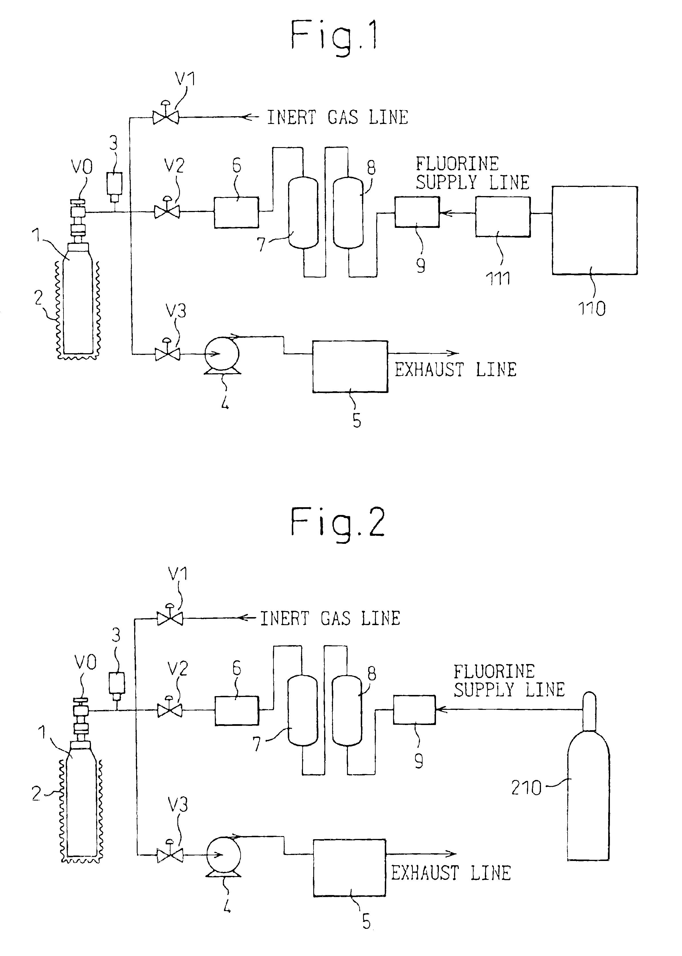
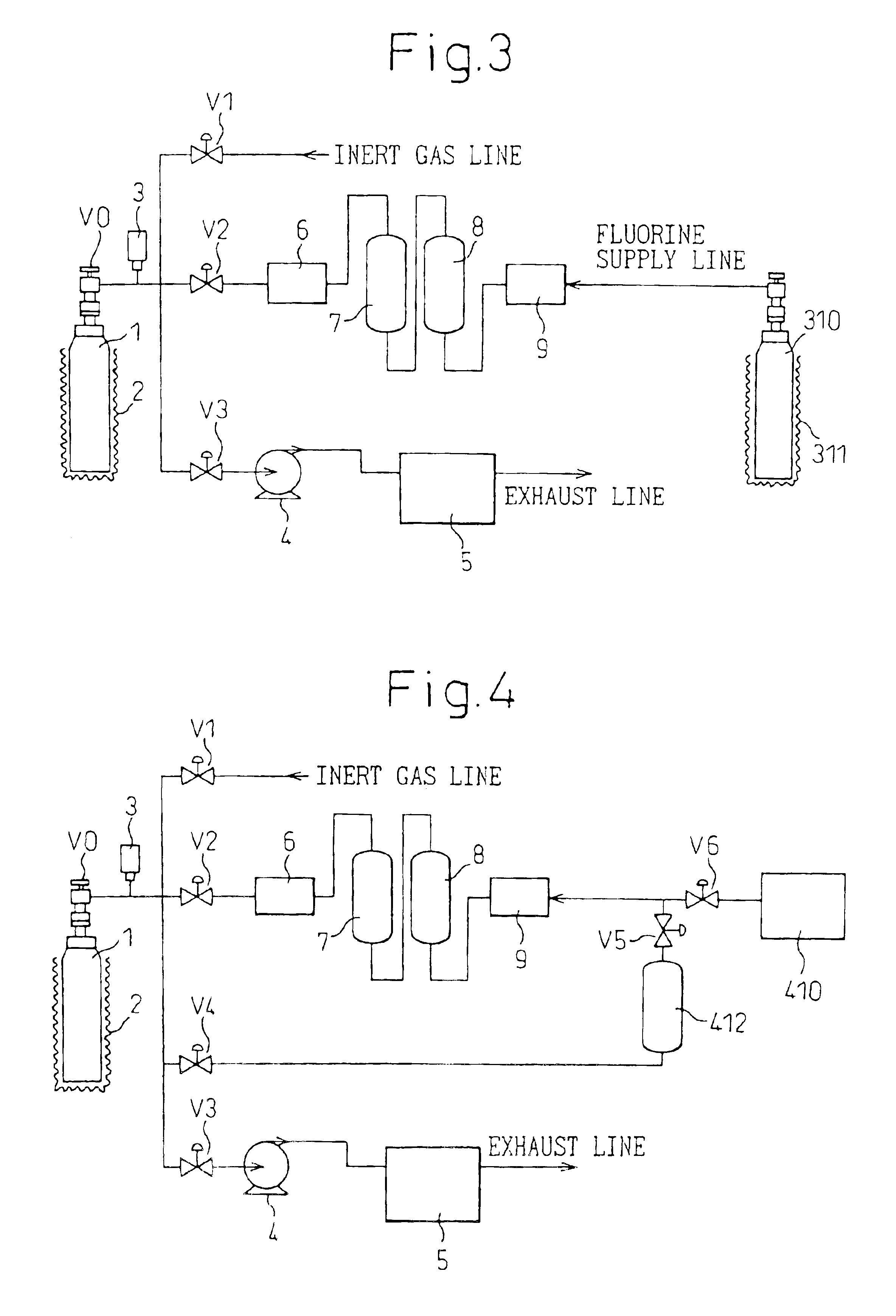
[0097]The apparatus shown in FIG. 4 was used and, as a fluorine supply source 410, an undiluted cylinder fluorine filled in a pressure-resistant container was used.

[0098]A monel 400-made fluorine generator 1 filled with a fluoronickel compound K3NiF7 was vacuum dried by an external heater 2 at a temperature of 150° C. under a pressure of 0.001 MPa (absolute pressure). The fluorine generator 1 was continuously depressurized by a vacuum pump 4 and under reduced pressure of 0.001 MPa (absolute pressure) and heated at 400° C. for 10 hours to release a fluorine gas. Then, from the fluorine cylinder 410, a fluorine gas was passed to a column 8 filled with sodium fluoride (NaF) at a flow rate of 100 ml / min and a crudely purified fluorine, after the removal of HF, was supplied directly to the fluorine generator 1 through a tank 7. As for the conditions at this time, the fluorine pressure was set to 0.4 MPa (absolute pressure) and the heating was externally performed to 250° C. Thereafter, t...

example 2

[0099]The fluorine generator 1 used in Example 1 was kept at a temperature of 350° C. and the generated fluorine was split into a previously vacuumized fluorine tank 412. Then, by closing the valve 4 and opening the valve 3, the fluorine occluded into the fluoronickel compound in the fluorine generator 1 was exhausted by a vacuum pump while heating at 350° C. to render the fluoronickel compound to be in a K3NiF6 state. The fluorine generator 1 was further continuously depressurized by a vacuum pump and under reduced pressure of 0.001 MPa (absolute pressure), heated at 400° C. for 10 hours. Subsequently, a fluorine gas was passed from the fluorine tank 412 to a column 8 filled with sodium fluoride (NaF) at a flow rate of 100 ml / min and the crudely purified fluorine, after the removal of HF, was supplied at 250° C. to the fluorine generator 1 through a tank 7.

[0100]The supply of fluorine gas was stopped, the temperature of heating the fluorine generator 1 was set to 200° C. and, while...

example 3

[0101]In order to further reduce the impurity gases, subsequently to Example 2, the fluorine generator 1 was heated at 250° C. for 1 hour under reduced pressure of 0.001 MPa (absolute pressure). Thereafter, the exhaustion by a vacuum pump was stopped and the heating temperature was elevated to 350° C. to obtain a fluorine gas. This fluorine gas was designated as Fluorine Gas (Example 3) and the analysis values thereof are shown in Table 1.

[0102]

TABLE 1PurityConcentration of Impurities [vol ppm][vol %]HFO2CO2N2CF4SiF4Example 199.8155011001001001010Example 299.95100300202055Example 3>99.9920


PUM

PropertyMeasurementUnit
pressureaaaaaaaaaa
temperatureaaaaaaaaaa

Abstract

A step (1) of heating a fluoronickel compound to release a fluorine gas, a step (2) of allowing a fluorine gas to be occluded into a fluorinated compound, and a step (3) of heating the fluoronickel compound and reducing an inner pressure are conducted in a container, respectively, at least once, and thereafter a high-purity fluorine gas is obtained in the step (1). Also, a step (5) of heating a fluoronickel compound and reducing an inner pressure and a step (6) of allowing a fluorine gas reduced in a hydrogen fluoride content to be occluded into the fluoronickel compound are conducted in a container having a fluorinated layer formed on its surface, respectively, at least once, the step (5) is further conducted, and thereafter a fluorine gas containing impurity gases is contacted with the fluoronickel compound to fix and remove the fluorine gas, and the impurities are analyzed by gas chromatography.

Description

CROSS-REFERENCE TO RELATED APPLICATIONS[0001]This application claims benefit pursuant to 35 U.S.C. §119(e)(1) of the filing date of the Provisional Application 60 / 306,421 filed Jul. 20, 2001, and the filing date of the Provisional Application 60 / 306,422 filed Jul. 20, 2001.[0002]This application is an application filed under 35 U.S.C. §111(a) claiming benefit pursuant to 35 U.S.C. §119(e)(1) of the filing date of the Provisional Application 60 / 306,421 filed Jul. 20, 2001, and the filing date of the Provisional Application 60 / 306,422 filed Jul. 20, 2001, pursuant to 35 U.S.C. §111(b).TECHNICAL FIELD[0003]The present invention relates to a high-purity fluorine gas, the production and use thereof, and a method for analyzing trace impurities in a high-purity fluorine gas. Particularly, the present invention relates to a process for producing a high-purity fluorine gas, a high-purity fluorine gas and a high-purity fluoronickel compound obtained thereby, and the use of the high-purity flu...

Claims


Application Information

Patent Timeline
Patent Type & Authority Patents(United States)
IPC IPC(8): C01B7/00C01B7/20G01N21/31G01N21/03G01N21/09G01N21/35G01N30/00G01N30/14H01S3/14H01S3/225H01S3/036
CPCC01B7/20G01N21/0303G01N21/09G01N21/3504Y10T436/19G01N2030/143H01S3/036H01S3/225
Inventor TORISU, JUNICHIATOBE, HITOSHIHOSHINO, YASUYUKI
Owner SHOWA DENKO KK
Why Eureka
Try Eureka