Flip chip underfill system and method

a chip and chip technology, applied in the direction of liquid transfer devices, non-printed electric components of printed circuits, transportation and packaging, etc., can solve the problems of only forming dots, requiring a template, and not being easily adaptable to changing application patterns, etc., to achieve constant flow rate and constant viscosity

Inactive Publication Date: 2005-10-18
NORDSON CORP
View PDF54 Cites 28 Cited by
  • Summary
  • Abstract
  • Description
  • Claims
  • Application Information

AI Technical Summary

Benefits of technology

[0013]The present invention provides a system for dispensing a viscous material onto a substrate which includes a dispensing element, a viscous material reservoir and a metering device coupled between the reservoir and the dispensing element for metering a variable amount of a viscous material through the dispensing element. The dispensing element and metering device can be moved by a positioner along a predetermined pattern adjacent a surface of a substrate. A weigh scale located adjacent the substrate receives a metered amount of the viscous material and produces signals representative of a variable weight of the material dispensed during a predetermined time interval. Thus a flow rate of material can be accurately determined. A controller adjusts a speed of movement of the positioner along the predetermined pattern to cause the dispensing element to dispense a desired amount of material based on a calculated flow rate. Alternatively, the controller adjusts a rate of delivery of the metering device based on the calculated flow rate to cause the dispensing element to dispense the desired amount of material along the predetermined pattern. Closed loop temperature control may be provided for the dispensing element and / or the substrate to ensure a substantially constant viscosity and a substantially constant flow rate. A prime and purge station may be provided adjacent the substrate for sucking air bubbles from the dispensing element and metering device.

Problems solved by technology

Screening requires a template and is not readily adaptable to changing application patterns.
Pin transfer is relatively fast but the tooling is expensive and inflexible and can only form dots, not lines.
Corrosion may result and thermal stresses may not be relieved.
If too much epoxy is deposited, it may flow beyond the underside of the chip and interfere with other semiconductor devices and interconnections.
However the viscosity of this type of adhesive changes rapidly with time as it cures, sometimes doubling within four hours of being thawed.
This complicates the task of dispensing, the correct amount of fluid, because if its viscosity increases too much, capillary action will not be sufficient to make it completely flow under the chip.
However, the prior art methods of controlling temperature in the conventional assembly of PC boards have not provided very accurate control of the viscosity.

Method used


Image

  • Flip chip underfill system and method
  • Flip chip underfill system and method
  • Flip chip underfill system and method

Examples


Embodiment Construction

[0019]The entire disclosure of pending U.S. patent application Ser. No. 08 / 192,709 filed Feb. 7, 1994 and entitled COMPUTER CONTROLLED VISCOUS FLUID DISPENSING SYSTEM is specifically incorporated herein by reference.

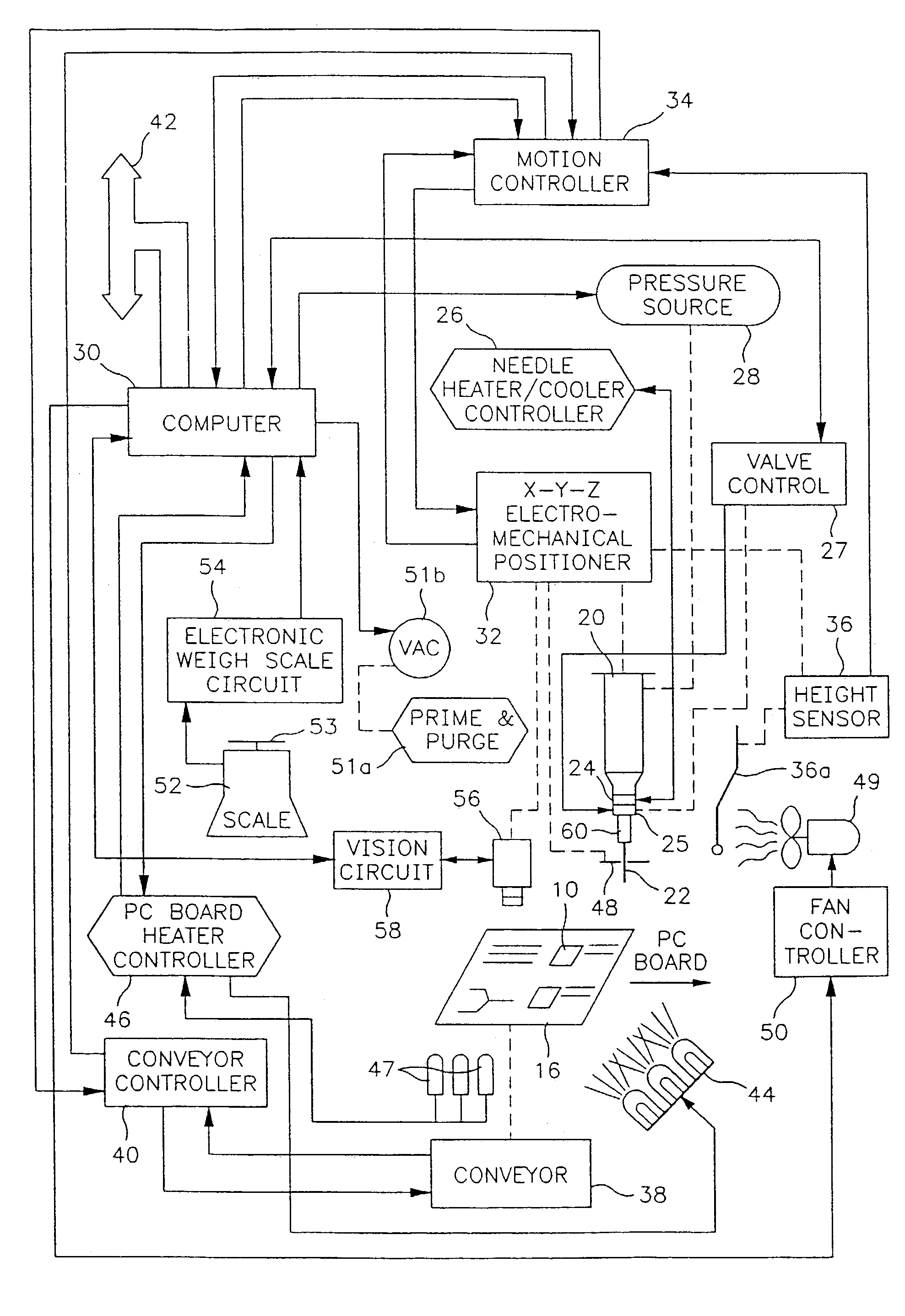
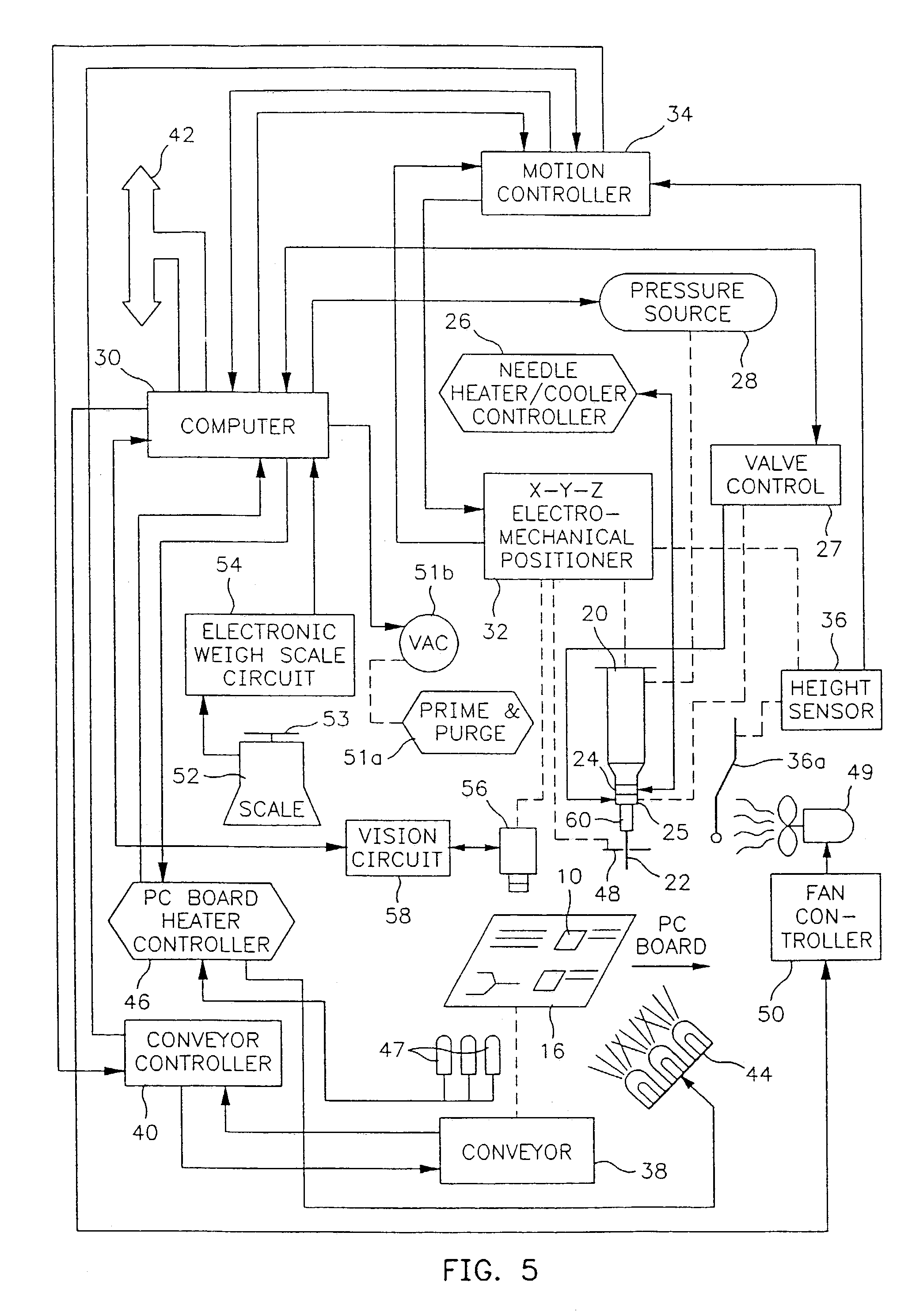
[0020]Referring to FIG. 5, our system includes a fluid reservoir in the form of a conventional disposable plastic syringe 20 connected to a dispensing element in the form of a needle 22. The needle 22 is surrounded by a heat sink 24 which includes separate resistive heating and temperature sensing elements (not illustrated). The heat sink 24 may also incorporate a cooling element (not illustrated) such as a Peltier diode. Alternatively, the heat sink may also incorporate a miniature vortex cooling generator which may be coupled to a source of pressurized air hereafter described. One suitable vortex generator is Part No. 3202 commercially available from Exair Corp.

[0021]The syringe 20 (FIG. 5) is coupled to the dispensing needle 22 through a metering device in the form of...


PUM

PropertyMeasurementUnit
viscosityaaaaaaaaaa
dispensing heightaaaaaaaaaa
diameteraaaaaaaaaa

Abstract

A system for dispensing a viscous material onto a substrate which includes a dispensing element, a viscous material reservoir and a metering device coupled between the reservoir and the dispensing element for metering a variable amount of a viscous material through the dispensing element. The dispensing element and metering device can be moved by a positioner along a predetermined pattern adjacent a surface of a substrate. A weigh scale located adjacent the substrate receives a metered amount of the viscous material and produces signals representative of a variable weight of the material dispensed during a predetermined time interval. A controller adjusts a speed of movement of the positioner along the predetermined pattern to cause the dispensing element to dispense a desired amount of material based on a calculated flow rate. Alternatively, the controller adjusts a rate of delivery of the metering device based on the calculated flow rate to cause the dispensing element to dispense the desired amount of material along the predetermined pattern. Closed loop temperature control may be provided for the dispensing element and/or the substrate to ensure a substantially constant viscosity and a substantially constant flow rate. A prime and purge station may be provided adjacent the substrate for sucking air bubbles from the dispensing element and metering device.

Description

[0001]This application is a continuation of application Ser. No. 09 / 273,479 filed Mar. 22, 1999 now U.S. Pat. No. 6,541,304 which is a divisional of application Ser. No. 08 / 963,993 filed Nov. 4, 1997 (now U.S. Pat. No. 5,906,682) which is a continuation of application Ser. No. 08 / 543,052 filed Oct. 13, 1995 (now abandoned).BACKGROUND OF THE INVENTION[0002]The present invention relates to automated equipment used in dispensing viscous materials. More particularly, the present invention relates to a system and method which in their preferred embodiments may be used for automatically dispensing the underfill epoxy used to attach silicon chips directly to printed circuit (“PC”) boards comprising FR4 or similar laminate substrates.[0003]In the manufacture of PC boards it is frequently necessary to apply small amounts of viscous materials, i.e. those with a viscosity greater than fifty centipoise. Such materials include, by way of example and not by limitation, general purpose adhesives, ...

Claims


Application Information

Patent Timeline
Patent Type & Authority Patents(United States)
IPC IPC(8): B05C11/10B05D1/26B05C5/00B05C5/02B05D7/00B67D7/08B67D7/18B67D7/82H01L21/56H05K1/18
CPCB05C11/10B05C5/0225H01L2224/16B05C11/1042B05C11/101B05C11/1013B05C11/1015B05C11/1018B05C11/1021
Inventor BOURAS, CARLOS E.LA., DUONG T.LEWIS, ALAN R.MEIER, MARK S.BABIARZ, ALEC J.
Owner NORDSON CORP
Why Eureka
Try Eureka