
System and method for enabling simultaneous calibration and imaging of a medium

Inactive Publication Date: 2005-10-18
THE GENERAL HOSPITAL CORP
View PDF4 Cites 98 Cited by
  • Summary
  • Abstract
  • Description
  • Claims
  • Application Information

AI Technical Summary

Benefits of technology

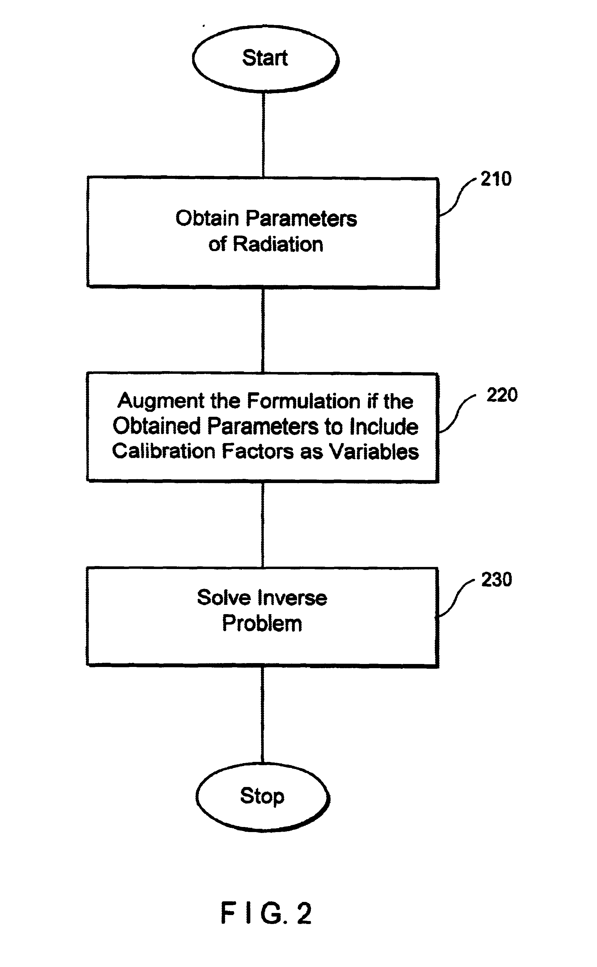
[0010]The present invention is preferably based on the fact that by allowing source and detector calibration factors to vary freely in the inverse calculation and be determined simultaneously with image reconstruction, image artifacts can be significantly reduced.
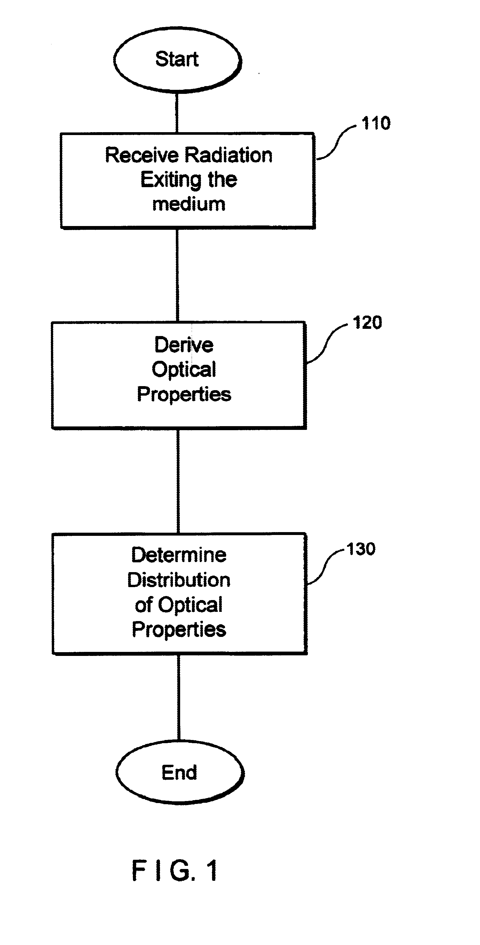
[0014]The or more of these optical properties can be derived by solving an inverse problem. The inverse problem can be solved by using, for example, a linear approximation model. One such exemplary linear approximation model used to derive the optical properties of the medium is a Born Approximation. Another exemplary linear approximation model is a Rytov Approximation. In the Rytov Approximation model, the measured parameter (e.g., fluence), is defined as an exponential of a perturbation on the background fluence. A specific implementation of an embodiment of the method of the present invention using the Rytov approximation involves minimizing a least-squares expression for the difference between the logarithms of the theoretical and measured fluence for each source-detector pair. The model can also scale the obtained parameters taken as input (e.g. fluence), to make those parameters dimensionless and to be on the same order as the calibration factors.
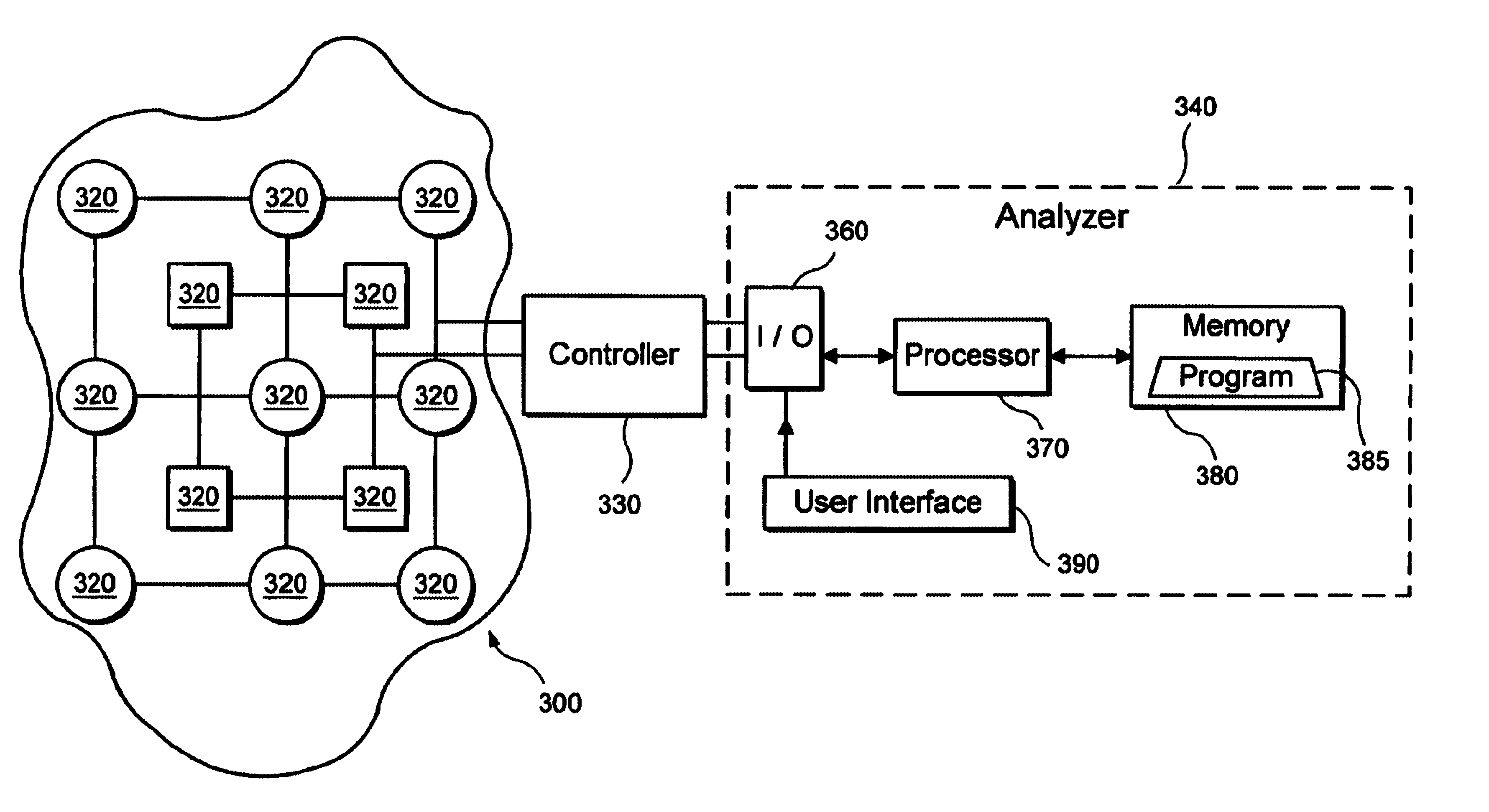
[0019]In addition, the property distribution determined by the system of the present invention can be provided as an image on a display, e.g., a computer screen. The model used to determine the property distribution can again be non-linear or linear. One such model includes the Rytov approximation and can involve, e.g., minimizing the square of the difference between the logarithms of the theoretical and measured fluence for each source-detector pair. The model can also utilize scaling parameters obtained from the signal as input to make them dimensionless and to be of the same order as the calibration factors.
[0023]In prior art systems and methods, several potential experimental systematic errors can hamper the ability to obtain images of the distribution of properties within a medium by applying radiation. While the characteristics of a system can be modeled prior to experimentation, slight fluctuations during experimentation, including for example changes in source strength or detector gain, can cause significant image artifacts. By including calibration in the image reconstruction algorithm, the present invention provides a substantial image improvement, despite the presence of possible considerable experimental systematic errors. One advantage of the methods and systems of the present invention is their ability to obtain diffuse optical tomography images having considerably reduced artifacts. The new imaging methods of the present invention can also be applied in electrical impedance tomography. These imaging methods can be utilized to image spatially varying optical properties of biological media, e.g., tissue, with enhanced contrast. In addition, such novel methods can be applied to image non-biological media (e.g., plastics, ceramics, or liquids) to detect defects or impurities using radiation. Other features and advantages of the invention will be apparent from the following detailed description, and from the claims. According to the present invention, the source and detector calibration factors can be allowed to vary freely in the inverse calculation and be determined simultaneously with image reconstruction, and thus image artifacts can be significantly reduced.

Problems solved by technology

Opaque media such as paint, milk, foam, emulsions, colloidal suspensions and human tissue do not strongly absorb visible light, while being optically turbid.
However, the measurements can include various errors caused by, for example, source and detector coupling to the tissue, source and detector positional uncertainties, fluctuations in the source power, and variations in the detector gain.
Unfortunately, errors can vary from a measurement to another measurement because of, e.g., the movement or perspiration of a patient or the movement of an optical fiber that forms part of a source or detector.
Thus, the results of an inverse calculation can include experimental systematic errors caused by measurement variations that are independent of the medium's properties of interest.
The experimental systematic errors can also limit absolute spectroscopic measurements of the optical properties at a particular spatial location, i.e., absolute, rather than relative, values of absorption and scattering.

Method used


Image

  • System and method for enabling simultaneous calibration and imaging of a medium
  • System and method for enabling simultaneous calibration and imaging of a medium
  • System and method for enabling simultaneous calibration and imaging of a medium

Examples


example 1

Simulation of Image Reconstruction

[0088]Several advantages of the methods of the present invention were demonstrated by simulations. The results obtained utilizing a normalized Rytov approximation without the reconstruction of calibration factors (i.e., without using the new calibration methods), a normalized Rytov approximation with reconstruction, a Born approximation with reconstruction, and a Rytov approximation without normalization were compared. A diagram of a first example of an experimental geometry is shown in FIG. 5.

[0089]The computer simulation involved the transmission through a 6-cm thick slab with background optical properties μso′=10 cm−1 and μao,=0.15 cm−1. A 1.6-cm diameter absorbing object 550 with μso′=10 cm−1 and μao=0.15 cm−1 was centered at (x, y, z)=(1, −1, 3) cm. Sixteen sources 510 were programmed in a four-by-four grid at z=0, spaced 2 cm apart to span x=−3 to 3 cm and y=−3 to 3 cm. Similarly, sixteen detectors 520 were located in a four-by-four grid at z=...

example 2

Phantom Results

[0105]The actual image results of a phantom have also been obtained, and FIG. 12 shows the experimental setup for imaging the phantom. A phantom box 1210 has a set of sources and a set of detectors on its top and bottom plates, respectively. The phantom box 1210 is connected with an RF Imager 1230 with a set of detector fibers 1220. The phantom box 1210 is also connected with a controller 1280 via a set of source fibers 1270. A processing arrangement 1290 is coupled with the controller 1280. The phantom box 1210 is further coupled with a beaker 1240 and a pump 1250.

[0106]The phantom box 1210 was filled with 0.5% intralipid solution, and a 2-cm diameter heterogeneity sphere was embedded in this solution. The content of the sphere was controlled by the circulation channel outside the phantom box 1210, which included the pump 1250 and the beaker 1240 for ink titration. In the experiment, a slab geometry was formed, with the slab having a thickness of 5.11 cm. The center ...


PUM


Abstract

The methods and systems are provided that alleviate the impact of experimental systematic errors. These calibration methods and systems can be based on the discovery that by including source and detector calibration factors as part of the inverse calculation for image reconstruction, image artifacts can be significantly reduced. The novel methods and systems enhance contrast in images of the distribution of the radioactive properties of a medium, and enable improved detection of, for example, spatial variations in optical properties within highly scattering media, such as human or animal tissue. The novel methods and systems receive radiation which exits from the medium. Then, one or more optical properties of the medium are derived using the received radiation and one or more calibration factors, wherein the calibration factors are variables. Subsequently, a distribution of the optical properties in the medium is determined using the derived optical properties.

Description

CROSS-REFERENCE TO A RELATED APPLICATION[0001]This application claims priority from the Provisional Appln. No. 60 / 261,492 filed on Jan. 12, 2001, the entire disclosure of which is incorporated herein by reference.STATEMENT AS TO FEDERALLY SPONSORED RESEARCH[0002]This invention was made with Government support under grants from the National Institutes of Health, NIH R29-NS38842 and NIH P41-RR14075, and the U.S. Army, No. DAMD17-99-2-9001. As a result, the Government of the United States of America has certain rights to the invention.TECHNICAL FIELD[0003]The invention relates to imaging, and more particularly to calibration of optical methods of imaging highly scattering media.BACKGROUND[0004]Opaque media such as paint, milk, foam, emulsions, colloidal suspensions and human tissue do not strongly absorb visible light, while being optically turbid. This turbidity is a result of a very short scattering length characteristic of photons traveling within these media. The light does not tra...

Claims


Application Information

Patent Timeline
IPC IPC(8): A61B5/00G01N21/47
CPCA61B5/0073A61B5/1495G01N21/4795A61B5/0091A61B2560/0233A61B2562/0233A61B2562/046
Inventor BOAS, DAVID A.CULVER, JOEARRIDGE, SIMONGAUDETTE, THOMAS
Owner THE GENERAL HOSPITAL CORP
Learn More