
Phase clock selector for generating a non-integer frequency division

a selector and phase clock technology, applied in the direction of generating/distributing signals, pulse techniques, horology, etc., can solve the problems of time-related system failure, more glitch-free switching, and complex prior art state machines requiring two counters

Inactive Publication Date: 2005-10-18
IBM CORP
View PDF11 Cites 19 Cited by
  • Summary
  • Abstract
  • Description
  • Claims
  • Application Information

AI Technical Summary

Benefits of technology

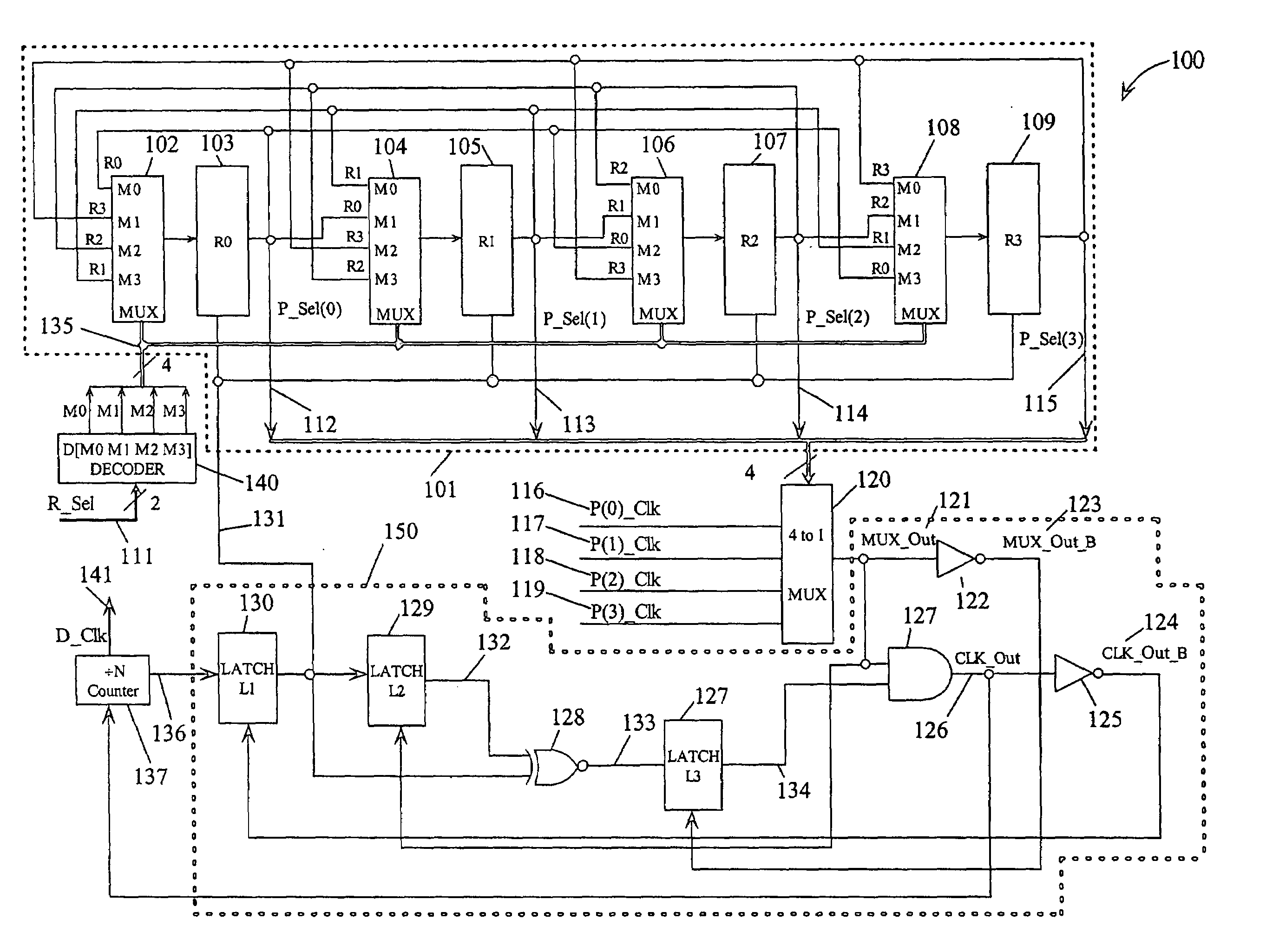
The present invention is a circuit and method for generating a frequency divided clock (FDC) from a multiphase clock. The FDC has a period that is a non-integer fraction of the multiphase clock. A glitch-free clock selector selects between the clock phases to generate a clock output signal. The clock output signal is used to clock a synchronous counter that produces a shift clock signal after N cycles of the clock signal. A select signal is decoded to determine what fraction P / k is desired for the fractional division of the clock. A rotate circuit generates "one hot" select signals for each of the clock phases. The k select signals are used in a feedback circuit to select the clock phases for the next N clock cycles. The technical effect of this invention is to provide a more efficient and accurate way to generate a FDC for use in synchronous circuits.

Problems solved by technology

Transients that occur on a clock in a computer system that is not one of the useable edges may be mistaken by the logic system as a valid clock edge and thus create timing problems or system failures.
However, if the two or more clocks are not synchronous, glitch-free switching is more difficult.
The prior art state machine is complex requiring two counters, a decoder, and another phase clock MUX.
However, there is no mechanism shown to perform the required phase switching.

Method used


Image

  • Phase clock selector for generating a non-integer frequency division
  • Phase clock selector for generating a non-integer frequency division
  • Phase clock selector for generating a non-integer frequency division

Examples


Embodiment Construction

[0020]In the following description, numerous specific details are set forth to provide a thorough understanding of the present invention. However, it will be obvious to those skilled in the art that the present invention may be practiced without such specific details. In other instances, well-known circuits may be shown in block diagram form in order not to obscure the present invention in unnecessary detail. For the most part, details concerning timing, data formats within communication protocols, and the like have been omitted inasmuch as such details are not necessary to obtain a complete understanding of the present invention and are within the skills of persons of ordinary skill in the relevant art.

[0021]Refer now to the drawings wherein depicted elements are not necessarily shown to scale and wherein like or similar elements are designated by the same reference numeral through the several views.

[0022]FIG. 1 is a non-integer fractional frequency divider (FFD) 100 according to e...


PUM


Abstract

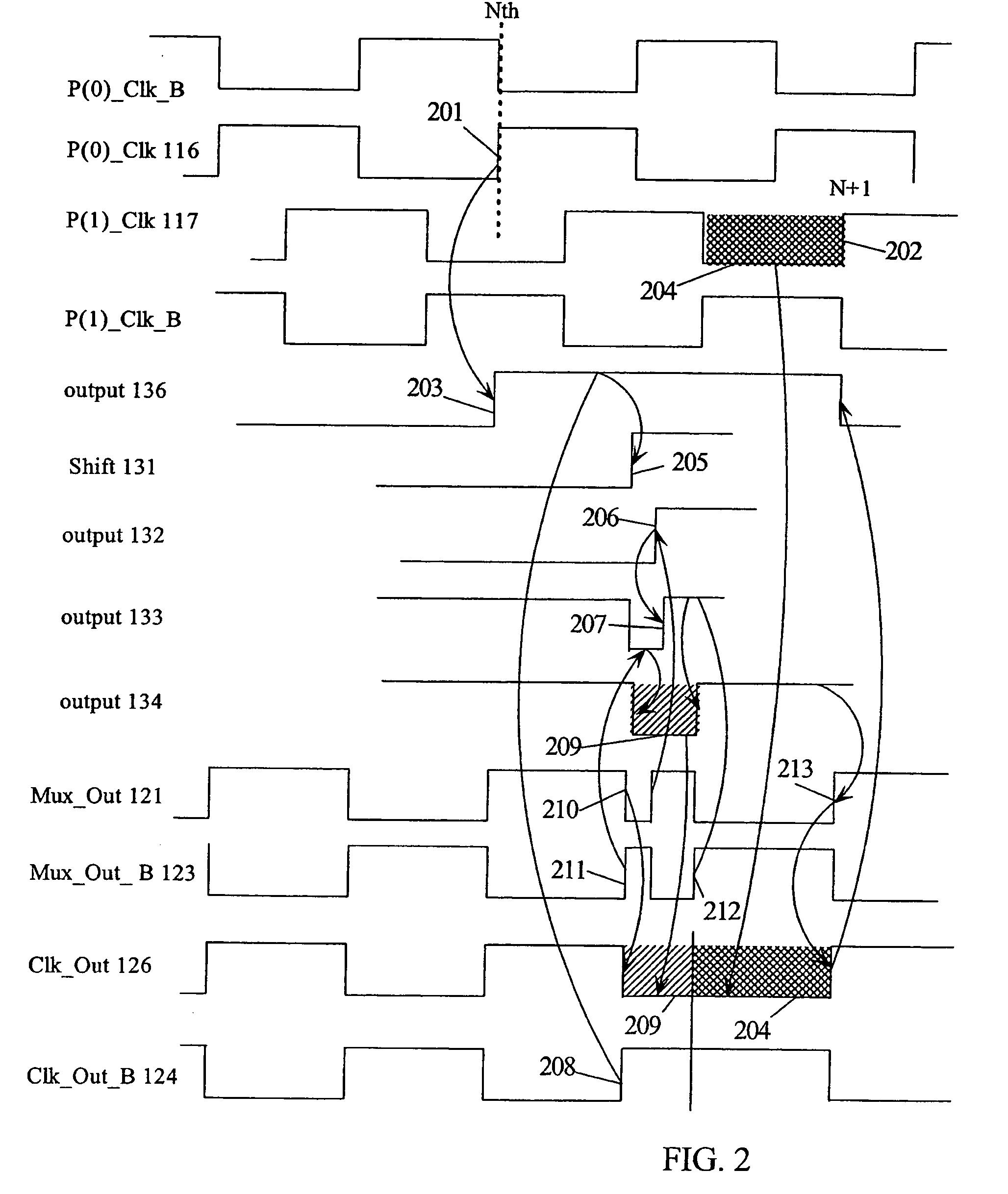
A frequency divider circuit uses a base counter to frequency divide a clock signal with period T by an integer value N and employs a cyclic rotational select circuit to select among multiple equally phase shifted signals of a multiple phase clock to generate a fractional term P / k where P is variable from 0 to k−1. The counter counts an output clock that corresponds to the output of a multiplexer selecting from among the multiple clock phases. Depending on the desired fractional term, after N counts of the output clock phases of the multiple phase clock are selected glitch free by rotationally selecting a first phase, and skipping either 0, 1, 2 . . . up to k−1 sequential phases to generate fractional terms 0, 1 / k, 2 / k, 3 / k . . . k−1 / k, respectively, thus providing frequency division corresponding to N+P / k where P may be varied from 0 to k−1.

Description

TECHNICAL FIELD[0001]The present invention relates in general to circuits for generating and controlling computer clocks and in particular to phase-locked loops for generating clocks using fractional division of a feedback clock.BACKGROUND INFORMATION[0002]Phase-locked loops (PLLs) have been widely used in high-speed communication systems because PLLs efficiently perform clock recovery or clock generation at a relatively low cost. Dynamic voltage and frequency scaling is a critical capability in reducing power consumption of power sensitive devices. Scaling, in this sense, means the ability to select high performance with nominal power supply voltages and high frequency clock operation or low performance by reducing the power supply voltage and corresponding the clock frequency. Reducing the system power is usually done when performance is not needed or when running from a limited energy source such as a battery. To allow low power operation, the PLL and other circuits must support ...

Claims


Application Information

Patent Timeline
Patent Type & Authority Patents(United States)
IPC IPC(8): G04G3/00G04G3/02H03K23/66H03K23/68H03L7/099H03L7/197
CPCG04G3/02H03K23/667H03K23/68H03L7/0996H03L7/1974
Inventor NGO, HUNG C.
Owner IBM CORP
Learn More