
Method and apparatus for dense motion field based coding

a motion field and motion field technology, applied in the field of motion estimation and compensation techniques, can solve the problems of increasing the bit rate required to encode this signal, increasing energy, and inaccuracy of compensation at the boundary of moving objects, so as to improve the quality of reconstructed images, improve performance, and eliminate certain blocking artifacts

Inactive Publication Date: 2005-10-18
LUCENT TECH INC +1
View PDF3 Cites 13 Cited by
  • Summary
  • Abstract
  • Description
  • Claims
  • Application Information

AI Technical Summary

Benefits of technology

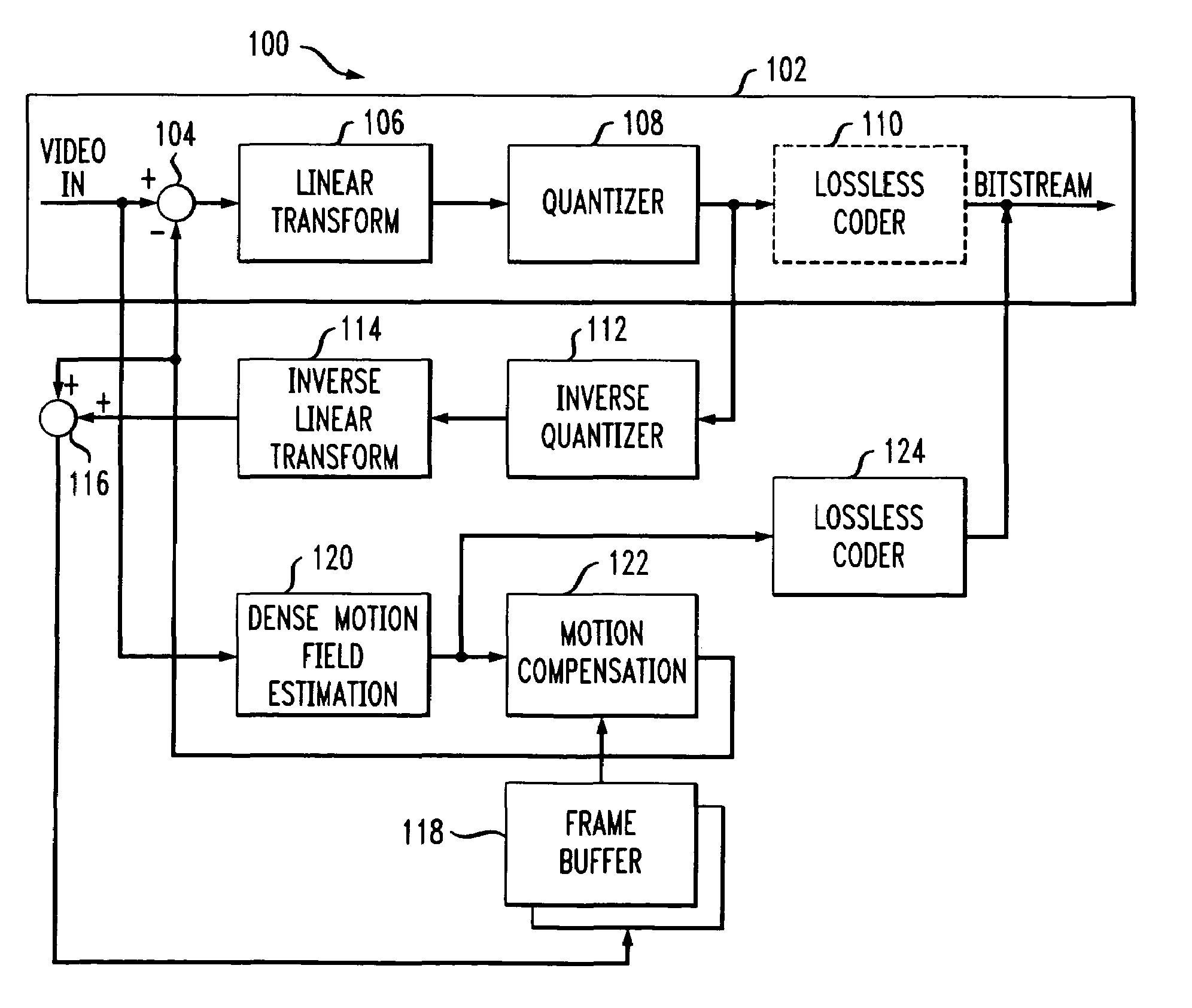
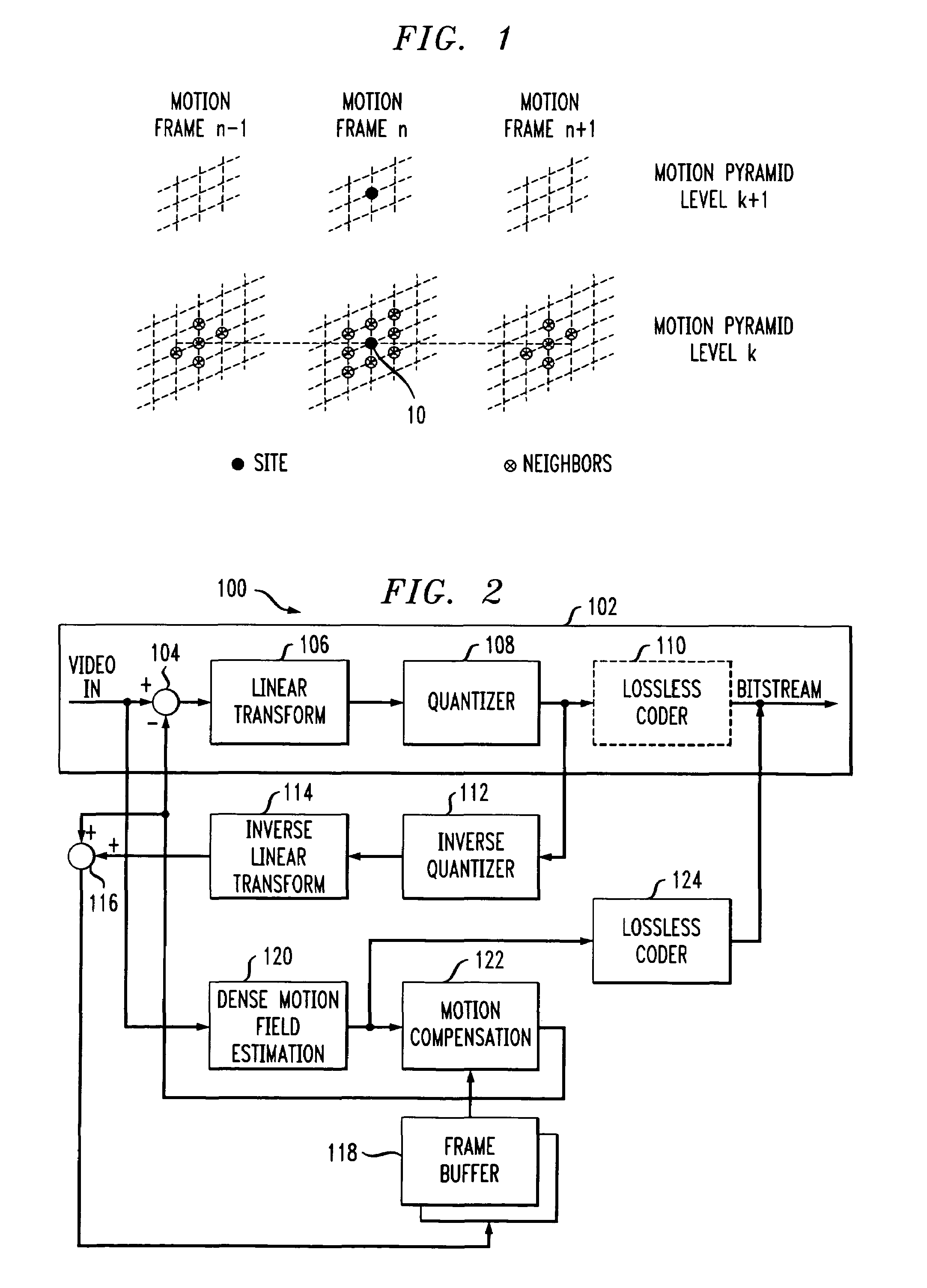
[0009]The invention provides video encoding techniques which perform motion estimation and compensation using a dense motion field rather than a block-based motion field. In accordance with the invention, an encoder generates an estimate of inter-frame motion utilizing a dense motion field in a sequence of video frames or other images. The estimate in an illustrative embodiment includes a motion vector for each pixel of the dense motion field. The estimate is generated at least in part as a solution to a constrained optimization problem based on a multiscale data model characterizing the motion between a given pixel in the dense motion field and neighboring pixels. The estimate is used for motion compensation in encoding the corresponding images, and is itself encoded for transmission to a decoder for use in decoding the encoded images. Advantageously, the constrained optimization based on the multiscale data model ensures that the set of motion vectors generated for the dense motion field can be efficiently coded for transmission to the decoder.
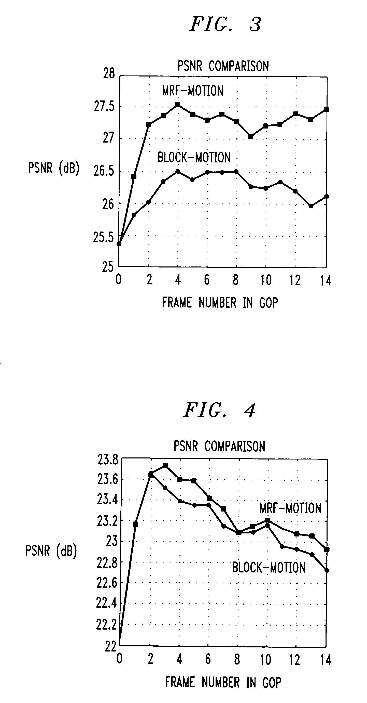
[0011]The invention can provide improved performance relative to conventional block-based coding, particularly for high-motion images. Moreover, the invention eliminates certain blocking artifacts commonly associated with block-based coding, resulting in higher quality reconstructed images. The invention is suitable for use in conjunction with a wide variety of different video encoding systems. These and other features and advantages of the present invention will become more apparent from the accompanying drawings and the following detailed description.

Problems solved by technology

Although it has been found in practice that acceptable video coding performance can be obtained using the above-described block-based motion estimation and compensation, there are inherent problems with this approach.
One significant problem is that since physical motion is not piecewise constant, inaccurate compensation can occur at the boundaries of moving objects.
As a result, there may be pixels within blocks containing non-uniform motion that are incorrectly compensated, and therefore a significant energy increase in the prediction error signal occurs, with a consequent increase in the bit rate necessary to encode this signal.
In addition, at low bit rates, when high quality coding of the prediction error is not possible, blocking artifacts may become clearly visible in the reconstructed video frames.
Furthermore, substantial efforts have been devoted over many years to optimizing block-based motion estimation and compensation, making it unlikely that significant performance gains remain to be achieved within that framework.

Method used


Image

  • Method and apparatus for dense motion field based coding
  • Method and apparatus for dense motion field based coding
  • Method and apparatus for dense motion field based coding

Examples


Embodiment Construction

[0015]The following description will illustrate the invention using an exemplary video encoder. It should be understood, however, that the invention is not limited to use with any particular type of signal format, encoding standard, encoder architecture or encoding system configuration. The invention is instead more generally applicable to any encoding application in which it is desirable to take advantage of temporal correlation between images. The term “image sequence” should be understood to include any frame sequence or other type of video sequence which is in a form suitable for encoding, e.g., suitable for encoding in accordance with standards such as H.261, H.263, Motion-JPEG, MPEG-1, MPEG-2, etc. The term “image” as used herein is therefore intended to include a frame or field of a video sequence.

[0016]The present invention provides image sequence encoding techniques which utilize motion estimation and compensation based on a dense motion field, rather than the block-based m...


PUM


Abstract

An encoder generates an estimate of apparent inter-image motion utilizing a dense motion field in a sequence of video frames or other images. The estimate in an illustrative embodiment includes a motion vector for each pixel of the dense motion field. The estimate is generated at least in part as a solution to a constrained optimization problem based on a multiscale data model characterizing the motion between pixels of the dense motion field and designated neighbor pixels. The estimate is used for motion compensation in encoding the corresponding images, and is itself encoded for transmission to a decoder for use in decoding the encoded images. In the illustrative embodiment, the multiscale data model characterizes spatial, temporal and scale coherence properties of the motion as a Markov random field (MRF), thereby ensuring that the resulting motion vectors can be efficiently coded for transmission to the decoder.

Description

RELATED APPLICATION[0001]The present application claims the benefit of U.S. Provisional Application No. 60 / 102,776, filed Oct. 2, 1998 and entitled “Stochastic Modeling and Entropy Constrained Estimation of Motion from Image Sequences.”FIELD OF THE INVENTION[0002]The present invention relates generally to video signal processing, and more particularly to motion estimation and compensation techniques for use in coding of video or other types of image sequences.BACKGROUND OF THE INVENTION[0003]Motion video sequences typically contain a significant amount of intra-frame or “spatial” redundancy as well as inter-frame or “temporal” redundancy. Video compression techniques take advantage of this spatial and temporal redundancy to reduce significantly the amount of information bandwidth required to transmit, store and otherwise process video sequences. For example, in the well-known MPEG-2 video encoding standard, described in greater detail in International Telecommunications Union, “Gene...

Claims


Application Information

Patent Timeline
IPC IPC(8): H04N7/12H04N7/26H04N7/50
CPCH04N19/61H04N19/53H04N19/537
Inventor PODILCHUK, CHRISTINE IRENESERVETTO, SERGIO DANIEL
Owner LUCENT TECH INC
Learn More