Single-step electromechanical mechanical polishing on Ni-P plated discs

a technology of electromechanical mechanical and ni-p plated discs, which is applied in the direction of lapping machines, manufacturing tools, and base layer manufacturing, etc., can solve the problems of two polishing steps, large substrate cost of consumables for polishing, and relatively time-consuming, so as to reduce the number of process steps, shorten the processing time, and reduce the effect of the consumable s

Inactive Publication Date: 2005-10-25
SEAGATE TECH LLC
View PDF7 Cites 44 Cited by
  • Summary
  • Abstract
  • Description
  • Claims
  • Application Information

AI Technical Summary

Benefits of technology

[0010]The purpose of this invention is to propose a method which reduces the number of process steps, shortens the p

Problems solved by technology

The fundamental problem is that at least two polishing steps are required to reduce a standard Ni—P plated substrate to a super-smooth finish.
These two polishing steps rely on chemical etching and mechanical abrasive action to remove Ni—P from the disc's surface and can be relatively time consuming.
As a result, the cost of consumables for polishing makes up a significant portion of the substrate co

Method used


Image

  • Single-step electromechanical mechanical polishing on Ni-P plated discs
  • Single-step electromechanical mechanical polishing on Ni-P plated discs
  • Single-step electromechanical mechanical polishing on Ni-P plated discs

Examples


Embodiment Construction

[0027]FIG. 7 shows a plan view of a disc drive in which the present invention is useful. The disc drive 2 includes a base member 4 to which the internal components of the disc drive unit are mounted. The base member 4 couples to a seal 6 and a top cover 8 which forms a sealed environment or cavity within the housing so established for the critical parts of the disc drive 2. The disc drive 2 includes one or more discs 10 which are mounted for rotation on the spindle motor generally indicated at 12. A magnetic read-write head 14, one for each disc surface, is mounted to an actuator 16. In the example shown here, the actuator 16 is a rotary actuator which moves the heads to a desired position on the surface of the disc.

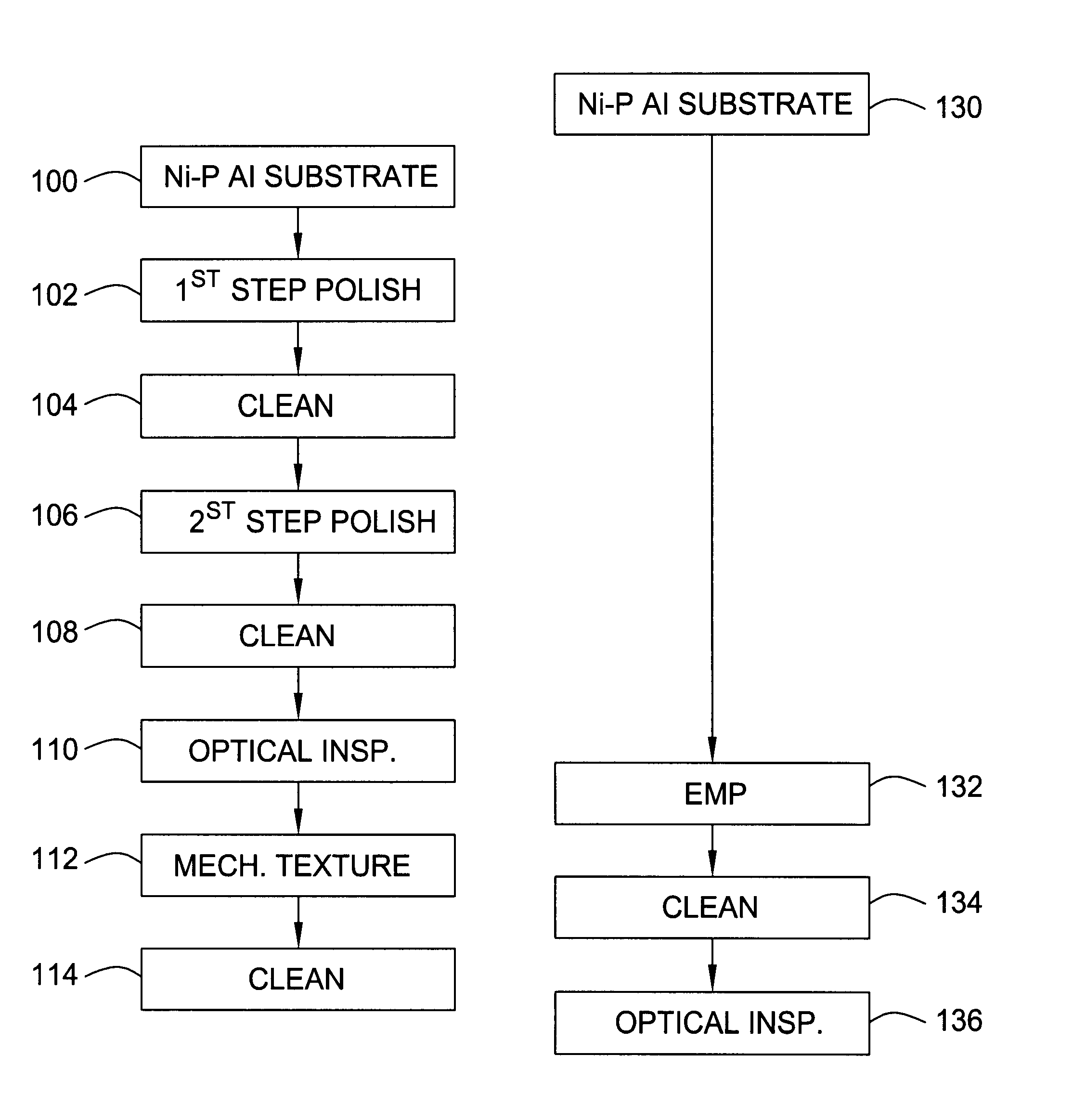
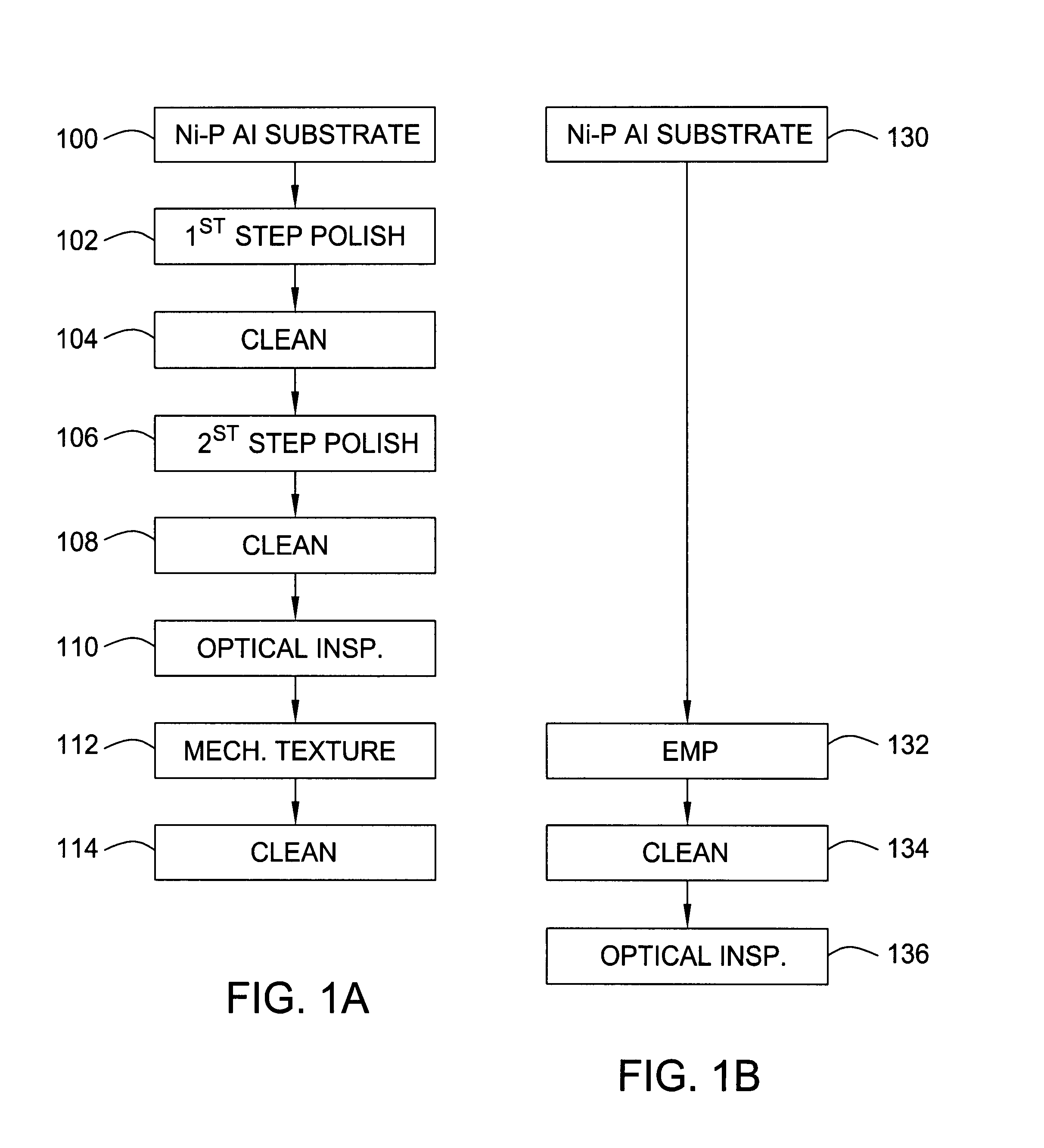
[0028]As is well known in this technology, it is essential to have smooth discs which typically comprise an aluminum substrate and a Ni—P layer which is circumferentially textured to enhance the magnetic recording properties of the recording layer.

[0029]FIGS. 1A and 1B c...


PUM

PropertyMeasurementUnit
Electrical conductoraaaaaaaaaa
Abrasiveaaaaaaaaaa
Mechanical propertiesaaaaaaaaaa

Abstract

Beginning with a smooth ground aluminum blank with a relatively thin layer of leveled Ni—P, circumferential electropolishing/texturing is carried out to achieve a smooth oriented surface. A conductive slurry is provided between the disc and a porous texturing tape which is in contact with a conducting plate or equivalent conductor. The disc serves as the anode, and the conducting plate as the cathode, while the slurry, being conductive, functions as an electrolyte. In the presence of current, a reverse electroplating occurs so that the Ni—P dissolves to form Ni2+, or nickel ions which are carried away by the conductive slurry. The conductive slurry further supports or carries therein abrasive material so that by moving the porous texturing tape past the disc surface, the texturing tape picks up the abrasive material in the slurry and simultaneously with the reverse electroplating, provides the desired mechanical abrasion to achieve texturing of the disc surface. The abrasive material comprises diamond particles. The circumferential electropolishing/texturing polish is achieved by spinning the disc while applying the mechanical-chemical action through the slurry system to the disc surface with electric current passing through the electrically conducting interface during processing.

Description

CROSS-REFERENCE TO A RELATED APPLICATION[0001]This invention is based on U.S. Provisional Patent Application Ser. No. 60 / 165,302 filed Nov. 12, 1999, entitled SINGLE-STEP ELECTROCHEMICAL MECHANICAL POLISHING ON Ni—P PLATED DISCS filed in the name of Joseph Leigh, Connie Liu and David Kuo. The priority of this provisional application is hereby claimed.FIELD OF THE INVENTION[0002]This invention relates generally to the field disc drive data storage devices, and more specifically the invention relates to an improved method for making the discs to be included in a disc drive storage device.BACKGROUND OF THE INVENTION[0003]Disc drive data storage devices are well known in the industry. Such devices use rigid discs coated with a magnetizable medium for storage of digital information on a plurality of circular concentric data tracks. The information is written to and read from the discs using a transducer head mounted on an actuator mechanism which moves the head from track to track across...

Claims


Application Information

Patent Timeline
IPC IPC(8): B24B1/00B23H5/08B24B21/00B24B37/04C25F3/02G11B5/84
CPCB23H5/08B24B21/00B24B37/042C25F3/02G11B5/8404
Inventor LEIGH, JOSEPHLIU, CONNIEKUO, DAVID
Owner SEAGATE TECH LLC
Why Eureka
Try Eureka