Speaker and speaker diaphragm

a technology of speaker and diaphragm, which is applied in the direction of transducer diaphragm, loudspeaker diaphragm shape, instruments, etc., can solve the problems of reducing the effective mass of the vibration system, and reducing the effect of the rib reinforcement or easiness of deformation

Inactive Publication Date: 2005-10-25
PIONEER CORP +1
View PDF23 Cites 33 Cited by
  • Summary
  • Abstract
  • Description
  • Claims
  • Application Information

AI Technical Summary

Benefits of technology

[0015]In order to accomplish the above object, according to a first aspect of the invention, there is provided a speaker including a frame; a diaphragm main body supported resiliently on the frame via an edge portion around outer circumference thereof; a groove rib integrally molded in the edge portion; and a regulation member provided on a part of the front or back face of the edge portion, and adapted to partially improve a flexural strength of the edge portion.
[0016]According to a second aspect of the invention, there is provided a speaker diaphragm including a diaphragm main body integrally formed with an edge portion around outer circumference thereof; a groove rib integrally formed in the edge portion; a regulation member provided on a part of the front or back face of the edge portion, and adapted to partially improve a flexural strength of the edge portion.
[0017]In the speaker and the speaker diaphragm configured above, the regulation member provided in the edge portion increases the effective mass of the vibration system, and decreases the low sound resonance frequency f0 by increasing m0 in the expression (1) for calculating the low sound resonance frequency f0. Accordingly, the lower stiffness s0 of the support portion of the vibration system and the increased effective mass m0 of the vibration system by disposing the ribs can cooperate to enhance the reproducing performance of low-sound range, thereby easily enhancing the reproducing capacity of low sound range. The regulation member provided in the edge portion may be disposed between the ribs formed on the edge portion or on the rib, whereby it is possible to extend the reinforcing effect of the rib to a wider range, or to supplement the drawback that occurs when the stiffness s0 is reduced, because the rib is reinforced over a local region having less flexural strength in the edge portion caused by an individual difference in assembling. Accordingly, the acceptable input is increased as compared with the conventional practice where the greater reproducing performance of low sound range relied only on reducing the stiffness s0, whereby the occurrence of the rolling is suppressed at the time of large input and the high quality reproduction with less distortion is realized.
[0018]Preferably, the regulation member may be formed by applying an adhesive or an agglutinant. In this manner, the hardness or weight of the regulation member is easily balanced by adjusting the amount of the adhesive or the agglutinant applied. Also, there is no need for increasing the number of parts.
[0019]More preferably, a plurality of the regulation members made of different materials may be provided. Also, a plurality of the regulation members having different sizes may be provided. In this manner, even if there is a minute difference in the reproducing performance between individuals owing to an assembling error or a tolerance of components, it is possible to make the fine adjustments for the reproducing performance to eliminate a dispersion in the reproducing performance between the products caused by individual differences in assembling, thereby stably producing the speaker that can make the high quality reproduction.
[0020]Preferably, the regulation member may be provided within a grooved portion of the groove rib. In this manner, the positioning operation in providing the regulation member is facilitated.

Problems solved by technology

Conventionally, a speaker of small diameter has been employed in an audio system for vehicle because of a limited installation space.
However, if the stiffness so is reduced excessively, the diaphragm main body causes the reproduced sound to be distorted, or gives rise to a rolling-that is a factor of causing the noise due to the mutual contact of a vibration mechanism, resulting in the risk of degrading the quality of reproduced sound.
Thereby, there was the problem that the reproducing capacity of low sound range could not be enhanced only by reducing the stiffness s0.
Further, an improved method of low sound range by forming the rib 3 had a drawback that since the rib 3 is intermittently disposed, the reinforcement or easiness of deformation of the rib 3 can not be attained uniformly over the entire area of the edge portion 1, and the edge portion 1 is fixed to the frame less uniformly over the entire circumference, whereby there is the possibility that the load on the edge portion 1 becomes maximum in a specific region due to a vibration propagation at the time of reproducing the sound.
Due to the above reasons, when an input signal was large (large input), or the diaphragm was made thinner, there was the risk that the quality of reproduced sound was degraded due to the rolling of the edge portion or the local distortion.
Also, there was the risk that the rolling might occur when the weight or compliance was unbalanced to lay a voice coil lead wire on the edge portion 1.

Method used


Image

  • Speaker and speaker diaphragm
  • Speaker and speaker diaphragm
  • Speaker and speaker diaphragm

Examples


Embodiment Construction

[0029]Referring now to the accompanying drawings, an embodiment of the invention will be explained in detail as follows.

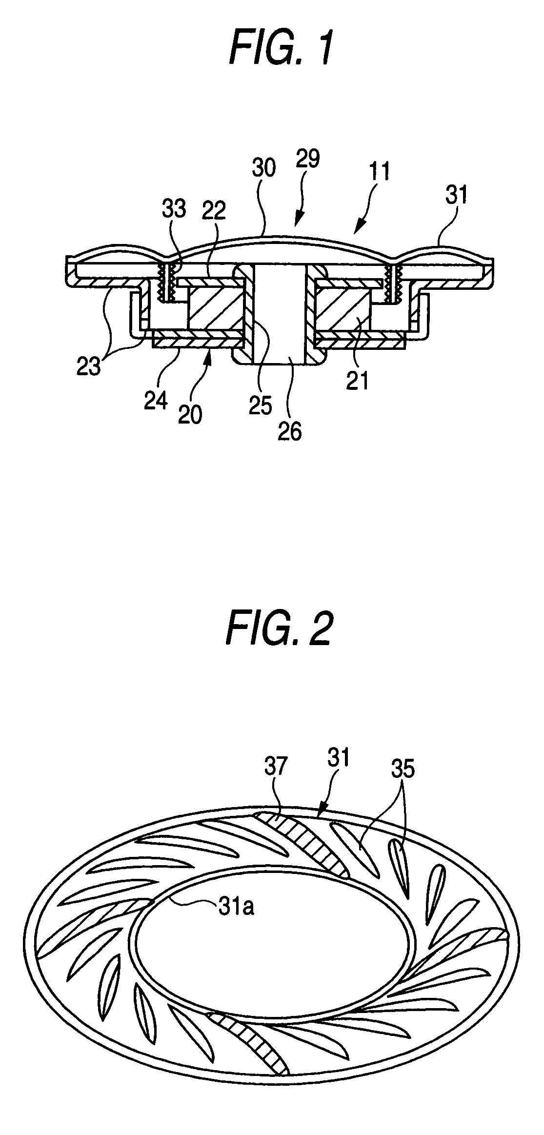
[0030]A speaker according to one embodiment of the present invention will be described below with reference to the accompanying drawings. FIG. 1 shows the speaker according to one embodiment of the invention.

[0031]The speaker 11 of this embodiment is employed in an audio system for vehicle, in which a magnetic circuit 20 is composed of a magnet 21, a pole piece 22, a yoke frame 23, and a base plate 24, in which a bore 25 is provided concentrically in the central portion thereof, and the magnetic circuit 20 is integrated by caulking both ends of an eyelet 26 inserted through the bore 25.

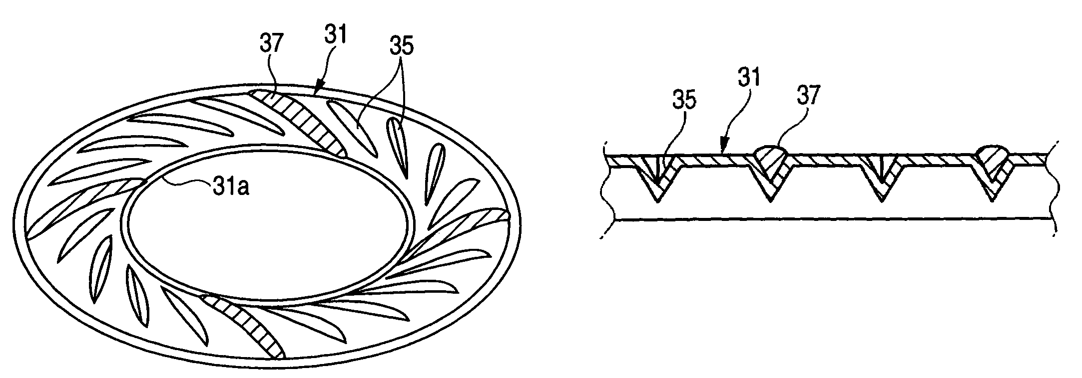
[0032]A diaphragm 29 is composed of a diaphragm main body 30 and a ring-like edge portion 31 leading to the outer circumference of the diaphragm main body 30. Because the outer circumferential edge of the edge portion 31 is joined with a rising portion around the outer circumference ...


PUM


Abstract

The speaker has a diaphragm main body 30 supported resiliently on a frame 23 via an edge portion 31 around its outer circumference, and the groove ribs 35 integrally formed in the edge portion 31, wherein a regulation member 37 for partially improving a flexural strength of the edge portion 31 is provided on a part of the front or back face of the edge portion 31.

Description

[0001]The present disclosure relates to the subject matter contained in Japanese Patent Application No. 2002-204689 filed on Jul. 12, 2002, which is incorporated herein by reference in its entirety.BACKGROUND OF THE INVENTION[0002]1. Field of the Invention[0003]The present invention relates to a speaker and a speaker diaphragm, and more particularly to a speaker of small diameter and a speaker diaphragm.[0004]2. Description of the Related Art[0005]Conventionally, a speaker of small diameter has been employed in an audio system for vehicle because of a limited installation space.[0006]The reproduction limit of low sound in the speaker depends on a low sound resonance frequency f0 as a rule of thumb, and this value is represented by the following expression (1),f0=(½π)(s0 / m0)1 / 2  (1)[0007]where m0(gr) is an effective mass of a vibration system, and s0(dyne / cm) is a stiffness (flexural rigidity (hardness) for enabling less vibration of a diaphragm main body) of a support portion for th...

Claims


Application Information

Patent Timeline
Patent Type & Authority Patents(United States)
IPC IPC(8): H04R7/20H04R7/00H04R7/18H04R7/02
CPCH04R7/20H04R2307/201H04R2307/207H04R2499/13
Inventor TAKAHASHI, OSAMUISHIYAMA, RYO
Owner PIONEER CORP
Why Eureka
Try Eureka