Active filter circuit with dynamically modifiable gain

a filter circuit and dynamic gain technology, applied in the field of signal processors, can solve the problems of complex implementation of analog floating point techniques and distortion of signal processor output, and achieve the effect of large dynamic rang

Inactive Publication Date: 2005-10-25
THE TRUSTEES OF COLUMBIA UNIV IN THE CITY OF NEW YORK
View PDF5 Cites 28 Cited by
  • Summary
  • Abstract
  • Description
  • Claims
  • Application Information

AI Technical Summary

Benefits of technology

[0005]It is therefore an object of this invention to provide a circuit which has a large dynamic range and ...

Problems solved by technology

However, this approach has the problem in that because the signal processor has memory, distortion in the output of the signal processor occurs whenever the amplification factors of t...

Method used


Image

  • Active filter circuit with dynamically modifiable gain
  • Active filter circuit with dynamically modifiable gain
  • Active filter circuit with dynamically modifiable gain

Examples


Embodiment Construction

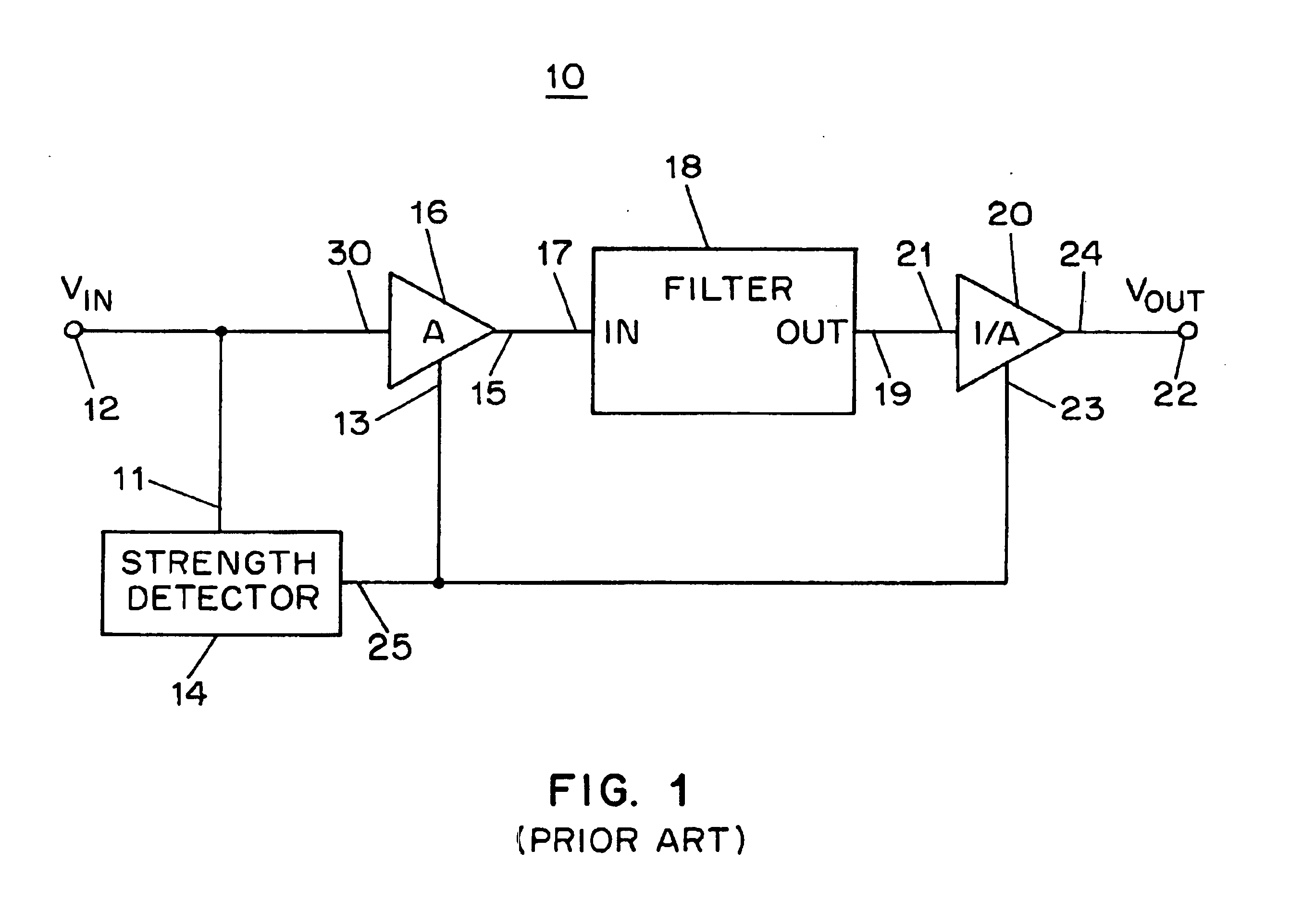
[0031]FIG. 1 illustrates an example of a prior art signal processing system 10. The signal processing system 10 is a companding filter. A companding filter amplifies or attenuates an input signal that is applied to a filter circuit, and attenuates or amplifies the output signal from the circuit. The prior art companding filter 10 includes an input 12, a signal strength detector 14, an input variable gain amplifier 16, a main filter 18, an output variable gain amplifier 20, and an output 22.

[0032]The input 12 of the signal processing system 10 is coupled to input 11 of the signal strength detector 14 and an input 30 of an input variable gain amplifier 16. The input variable gain amplifier 16 amplifies or attenuates the signal received by the input 30 depending on a gain control input signal received at a gain control input 13 of the input variable gain amplifier 16 and outputs the resultant signal at its output 15. The output 15 of the input variable gain amplifier 16 is coupled to i...


PUM


Abstract

A signal processing system (100) comprises an input terminal (102), and a main path having a main filter input gain unit (126) coupled to said input terminal (102), a main filter (132) and an output gain unit (138). An auxiliary path includes an auxiliary filter input gain unit (106) coupled to the input terminal (102), an auxiliary filter (112) and an auxiliary filter output gain unit (118). An adder (144) is coupled to the output gain units (118, 138) for generating an output signal to an output terminal (148). The gains of the gain units are adjusted by a control unit (18) responsive to a detecting signal from a detector (160).

Description

[0001]This application claims priority to U.S. Provisional Application Ser. No. 60 / 260,722 filed Jan. 10, 2001, and U.S. Provisional Application Ser. No. 60 / 288,976 filed May 4, 2001, each of which is incorporated by reference herein in its entirety.BACKGROUND OF THE INVENTION[0002]The present invention relates to signal processors and, more particularly, to signal processors that are dynamically modifiable for optimal performance and reduced power dissipation.[0003]In order to expand the dynamic range of a signal processing system, companding signal processors can be used. A companding signal processor uses an input amplifier to amplify or attenuate a signal before it is provided to the signal processor, and an output amplifier is used to amplify or attenuate the signal provided by the signal processor. A signal processor or signal processing circuit includes an active filter. The gain of the output amplifier is the inverse of the gain of the input amplifier, thus conserving the ov...

Claims


Application Information

Patent Timeline
IPC IPC(8): H03F1/00H03K5/00H03B1/00H03G1/04H03G3/00H03G5/00H03G7/00H03H11/04H03H11/12
CPCH03G1/04H03G3/001H03G7/00H03H11/04H03H11/126H03H11/1291H03H11/1256H03H11/1252
Inventor PALASKAS, GEORGETSIVIDIS, YANNISTOTH, LASZLO
Owner THE TRUSTEES OF COLUMBIA UNIV IN THE CITY OF NEW YORK
Why Eureka
Try Eureka