Biochannel assay for hybridization with biomaterial

a biomaterial and assay technology, applied in the direction of material analysis, fluid speed measurement, optical light guide, etc., can solve the problems of single base mismatch, single base mismatch, and inability to control the stringency of each individual probe site, so as to improve the stringency control of hybridization and shorten the assay time , the effect of increasing the rate of hybridization

Inactive Publication Date: 2005-11-01
CLINICAL MICRO SENSORS +1
View PDF155 Cites 65 Cited by
  • Summary
  • Abstract
  • Description
  • Claims
  • Application Information

AI Technical Summary

Benefits of technology

[0020]The microchannels may have a variety of configurations, feedback arms, valves, and vents to control fluid flow. There may be single or multiple channels. The invention provides for efficient contact between immobilized binding substances and binding partners in the fluid flowing through the channel. The invention provides for improved hybridization stringency control by flow modulation; shortened assay time by increasing the rate of hybridization with flow induced agitation and by bringing the target and probe into proximity within the microfluidic channel; and increased hybridization efficiency which improves sensitivity. In addition there is no interference through hydrolysis.

Problems solved by technology

A common challenge to all DNA hybridization technologies is the lack of control of stringency for each individual probe site.
For DNA probe arrays, since the DNA probe sequences are different, hybridization recognition is never perfect under a uniform stringency condition for the entire probe array.
The problem is most obvious for short duplexes which often results in single base mismatches.
In addition, the current DNA array technologies have failed to provide an effective solution to maximize hybridization efficiency.
The binding of probes to the microchannel wall does not provide for optimum contact of probe and test sample.

Method used


Image

  • Biochannel assay for hybridization with biomaterial
  • Biochannel assay for hybridization with biomaterial
  • Biochannel assay for hybridization with biomaterial

Examples


Embodiment Construction

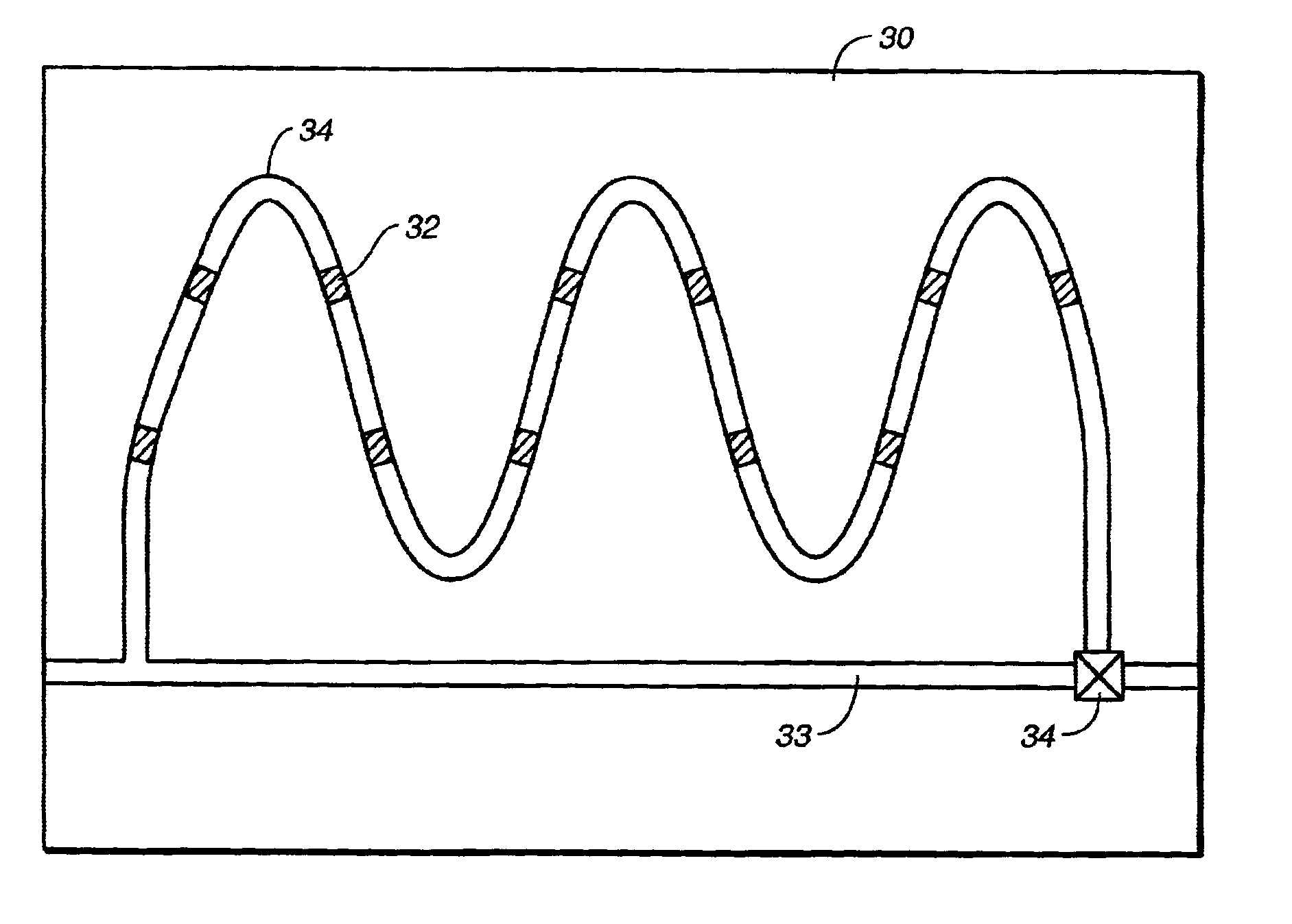
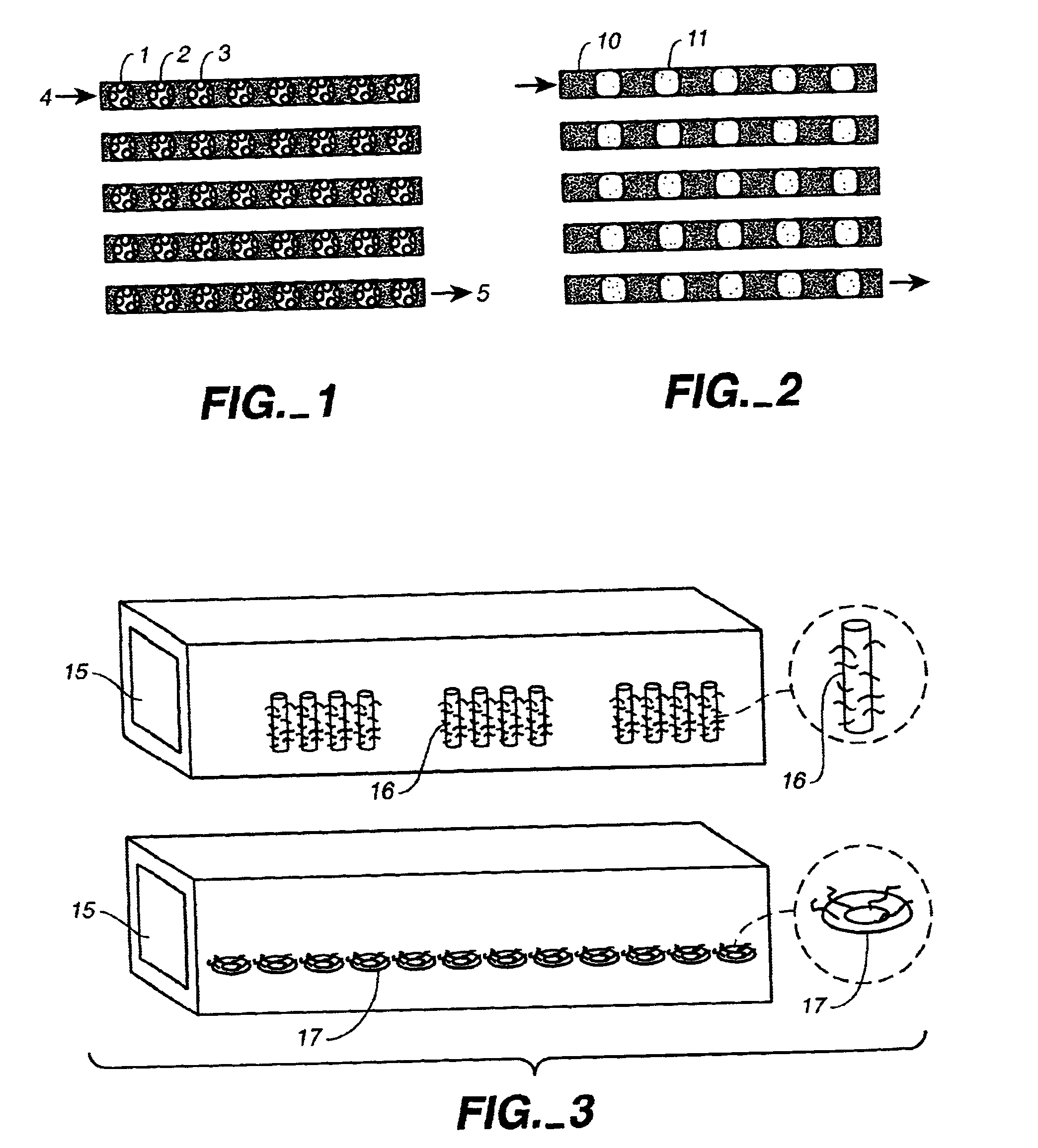
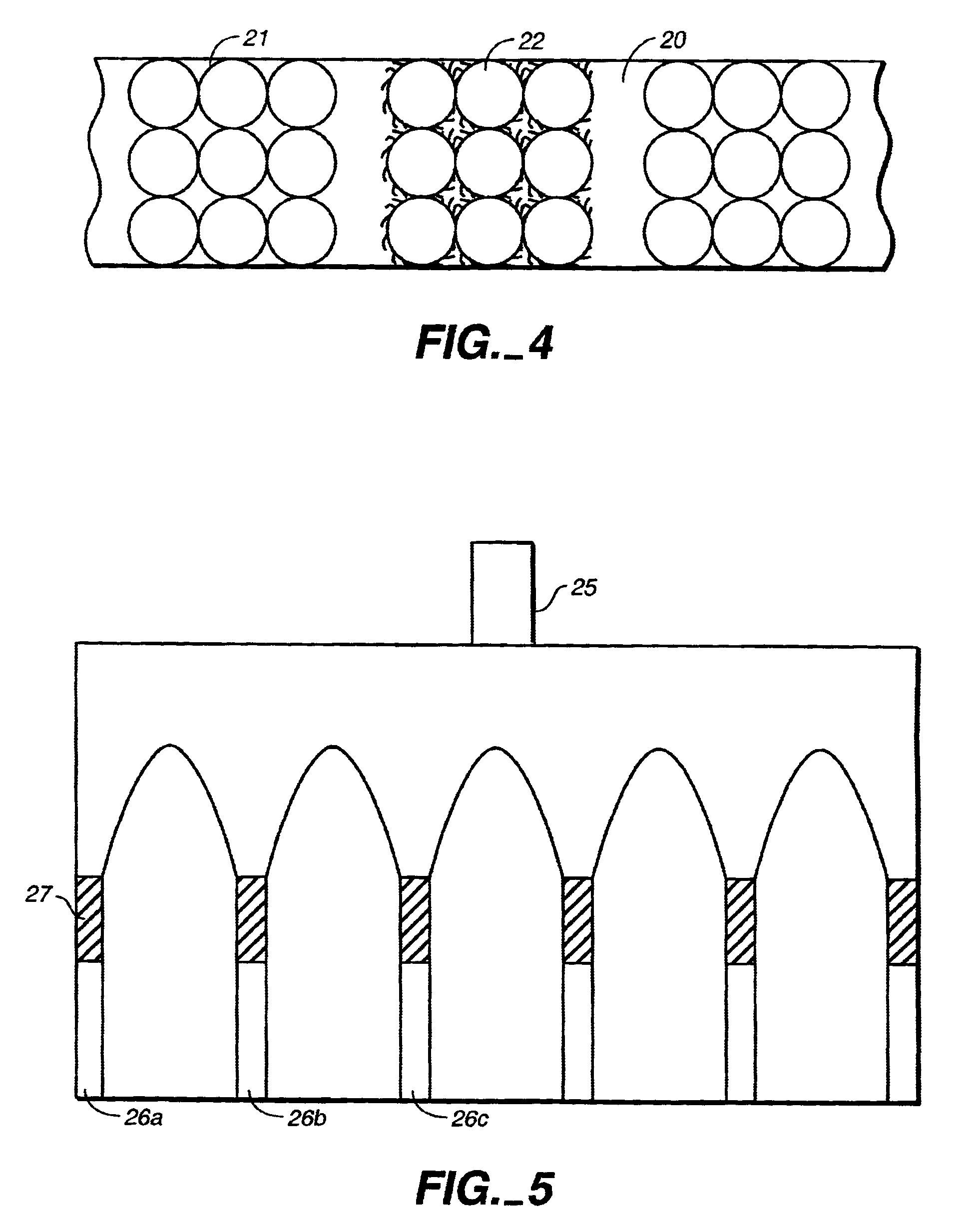
[0021]The chips microfluidic channels of the present invention are channels generally less than 200 microns in plastic with molding or embossing technology. The channels need to be of the dimension to support pumping of the microfluidic system The microfluidic channel may have any shape, for example, it may be linear, serpentine, arc shaped and the like. The cross-sectional dimension of the channel may be square, rectagular, semicircular, etc. There may be multiple and interconnected microchannels with valves to provide for recirculation.

[0022]The section of solid material maybe chips made of glass, ceramic, metal, silicon or plastic. Chips are preferably fabricated from plastics such as expoxy resin, polyacrylic resins, polyester resins, polystyrene, polycarbonate, polyvinyl chloride and the like. Specific binding pairs are DNA / DNA or DNA / RNA complementary binding pairs.

[0023]Fluid propelling components such as pressurized gas, vacuum, electric field, magnetic field and cetrifugal ...


PUM

PropertyMeasurementUnit
flow rateaaaaaaaaaa
microstructuresaaaaaaaaaa
electrical fieldaaaaaaaaaa

Abstract

The invention relates to a microfluidic device with microchannels that have separated regions which have a member of a specific binding pair member such as DNA or RNA bound to porous polymer, beads or structures fabricated into the microchannel. The microchannels of the invention are fabricated from plastic and are operatively associated with a fluid propelling component and detector.

Description

[0001]This application is, a continuation of U.S. Ser. No. 09 / 438,600, filed Nov. 12, 1999, now U.S. Patent No. 6,361,958, issued Mar. 26, 2002, and is hereby incorporated by reference in its entirety.BACKGROUND OF THE INVENTION[0002]1. Field of the Invention[0003]The invention pertains to the structure, fabrication of a microfluidic device and methods for conducting analysis in microfluidic devices.[0004]2. Background of the Art Related to the Invention[0005]Analysis utilizing specific binding pairs such as antigen / antibody; complementary DNA / DNA; DNA / RNA; RNA / RNA; biotin / avidin containing pairs are widely known in the art. Techniques for manufacturing and utilizing microfluidic devices are also well known. The art also discloses various techniques for DNA sequencing based on complementary binding of DNA.[0006]DNA probe array technology, which utilizes binding of target single standed DNA onto immobilized DNA probes has wide applications. A large amount of research and development ...

Claims


Application Information

Patent Timeline
Patent Type & Authority Patents(United States)
IPC IPC(8): B01L3/00B01L7/00C12Q1/68G01N33/53B01J19/00B81B1/00C12M1/00C12N15/09C40B40/06C40B40/10C40B60/14G01N33/566G01N37/00
CPCB01L3/5027B01L7/525B82Y30/00C12Q1/6834B01J2219/00317B01J2219/00351B01J2219/00416B01J2219/00418B01J2219/00421B01J2219/00432B01J2219/0052B01J2219/00522B01J2219/00585B01J2219/00596B01J2219/00605B01J2219/0061B01J2219/00621B01J2219/00644B01J2219/00648B01J2219/00659B01J2219/00707B01J2219/00711B01J2219/00722B01J2219/00725B01L3/502707B01L2300/0636B01L2300/0816B01L2300/087B01L2400/0415B01L2400/043B01L2400/049C40B40/06C40B40/10C40B60/14C12Q2565/629Y10S366/02Y10S435/81
Inventor SHIEH, CHAN-LONGFOLEY, BARBARAYU, HUINANCHOONG, VI-EN
Owner CLINICAL MICRO SENSORS
Why Eureka
Try Eureka