
Glass crack prevention film-like layer and plasma display device

a technology of glass crack prevention and filmlike layer, which is applied in the direction of film/foil adhesive, gas-filled discharge tube/lamp details, discharge tube/lamp details, etc., can solve the problems of high cost, heavy weight of plasma display device, double image, etc., and achieve the reduction of weight, thickness and cost of display device, and the elimination of air layer

Inactive Publication Date: 2005-11-01
NITTO DENKO CORP
View PDF14 Cites 9 Cited by
  • Summary
  • Abstract
  • Description
  • Claims
  • Application Information

AI Technical Summary

Benefits of technology

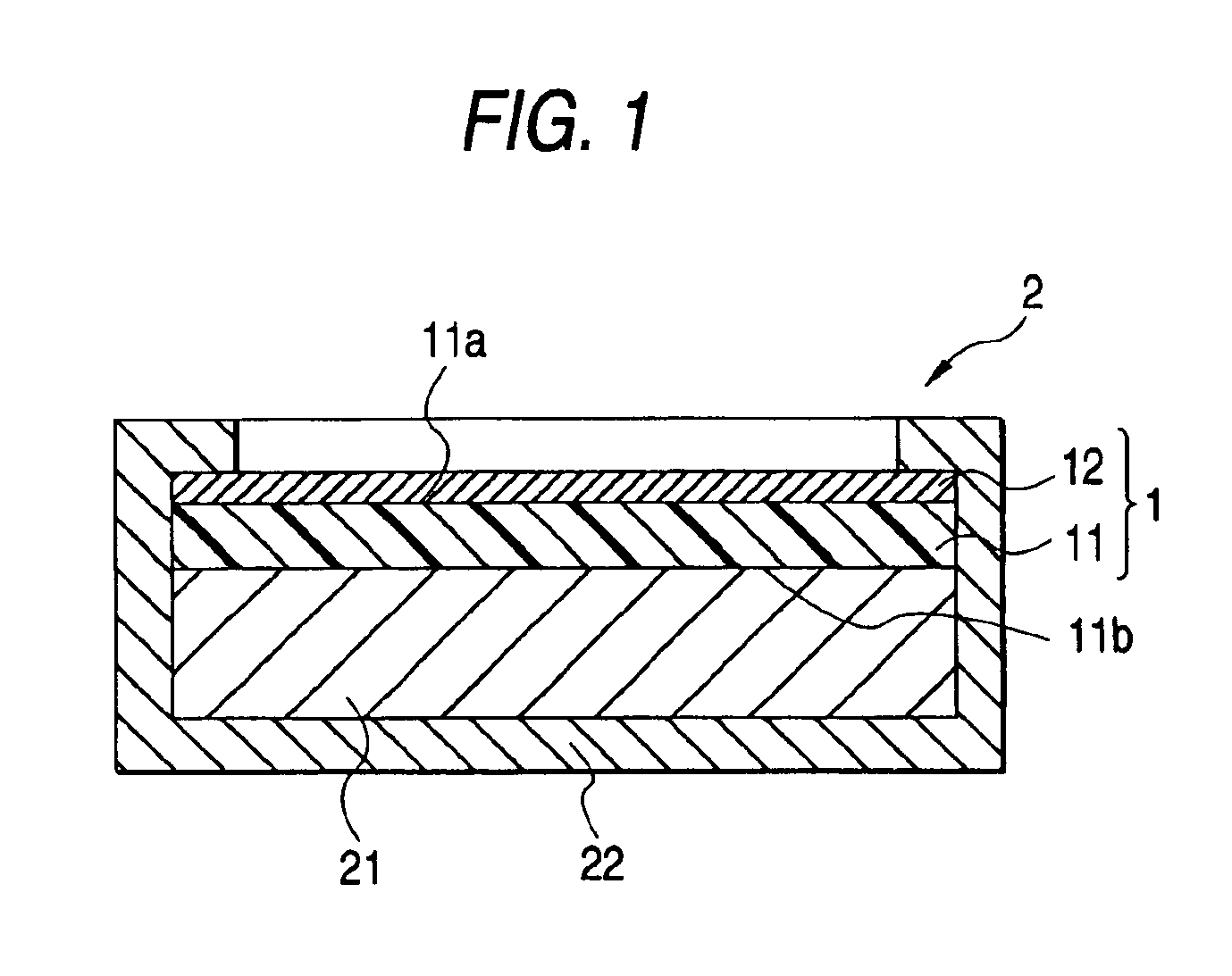
[0045]FIG. 2 shows an example of the lamination. That is, FIG. 2 shows the case where a functional film 13 having a function of shielding electromagnetic waves and / or near-infrared rays is laminated between the anti-reflection film 12 and the glass crack prevention layer 11 when the anti-reflection film 12 is laminated on one surface 11a of the glass crack prevention layer 11. As for the electromagnetic wave shielding function, it is preferable that the shielding effect is not lower than 10 dB, especially not lower than 20 dB. As for the near-infrared ray shielding function, it is preferable that transmittance with respect to near-infrared rays (in a wavelength range of from 800 to 1,200 nm) is not higher than 20%, especially not higher than 10%. Any known film can be widely used as the functional film 13 but the total thickness of the functional film 13 and the anti-reflection film 12 is preferably selected to be in a range of from 0.01 to 0.5 mm, especially in a range of from 0.05 to 0.3 mm so as not to disturb the effect of the invention. Alternatively, the functional film 13 may be disposed below the glass crack prevention layer 11.
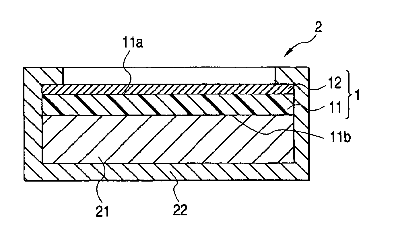
[0046]In the plasma display device 2, the glass crack prevention film-like layer 1 configured as described above is directly stuck onto the visual side of the plasma display panel 21 constituted by one glass substrate or two glass substrates, by use of the adhesive face which is a surface 11b (opposite to one surface 11a) of the glass crack prevention layer 11 on which the anti-reflection film 12 (or together with the functional film 13) is laminated, so that the glass crack prevention film-like layer 1 is attached to the plasma display panel 21. When the filter 1 is attached to the display panel 21 in this manner, external impact applied on the display panel 21 is absorbed to and relaxed by the glass crack prevention layer 11 in the filter 1. Hence, glass in the display panel 21 can be effectively prevented from being broken by external impact.
[0047]Moreover, the air layer formed in the related art is needless because the filter 1 is directly attached to the plasma display panel 21. Hence, the double image problem caused by the air layer can be eliminated. In addition, the attachment operation is easy enough to make great contribution to reduction in weight, thickness and cost of the display device because the filter 1 is formed to have the relatively thin and light weight anti-reflection film 12 (or together with the functional film 13) laminated therein. In the configuration in which the adhesive face provided as the other surface 11b of the glass crack prevention layer 11 in the filter 1 has re-releasablity, there is a further effect that the filter 1 can be removed easily because the filter 1 is removable for recycling when the plasma display device needs to be disposed of.
[0048]The invention will be described below more specifically by way of example. Incidentally, the term “parts” in the following description means “parts by weight”.

Problems solved by technology

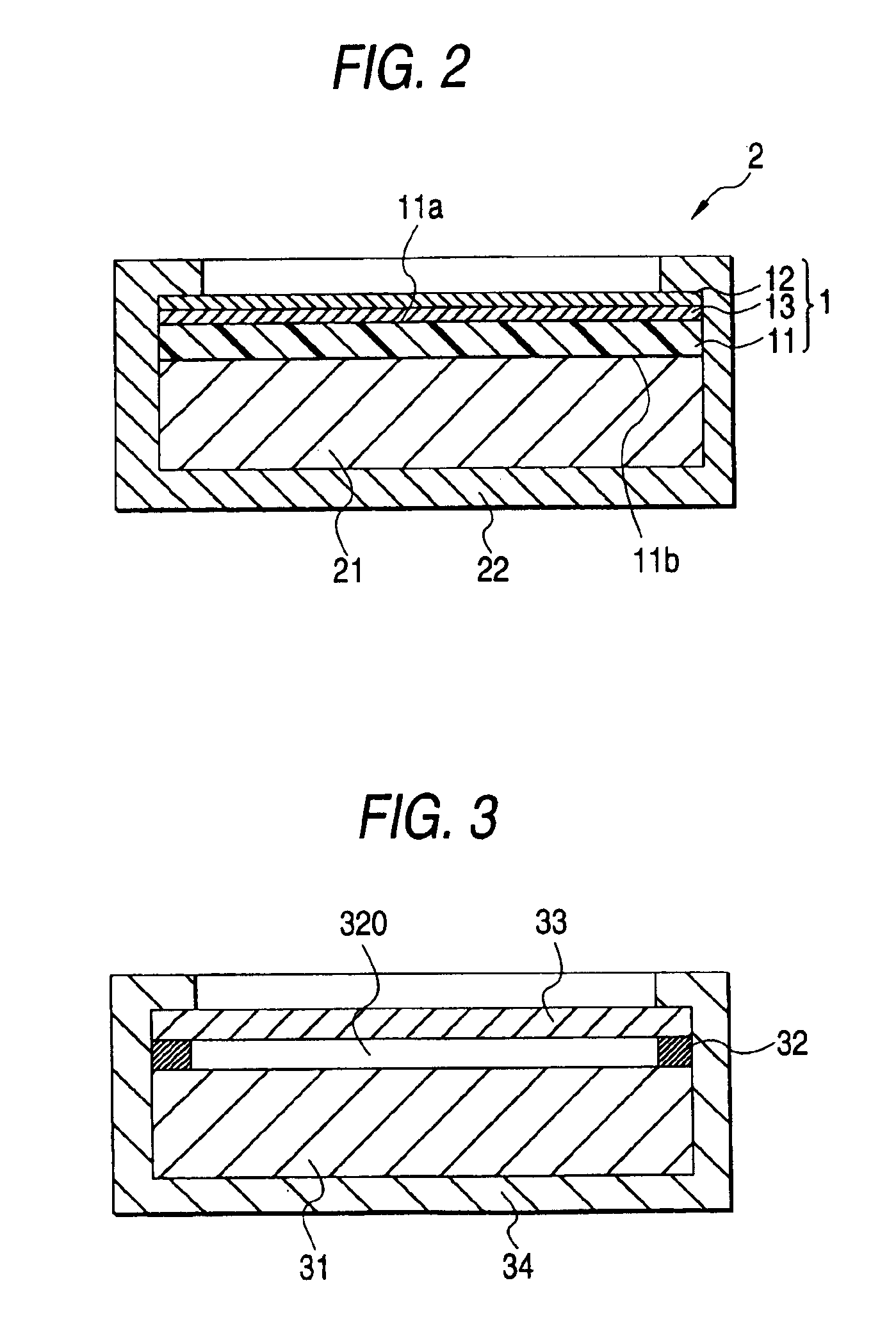
There is, however, a problem that an image is doubled because of refraction of light in the interfaces between an air layer made up of the gap 320 and the plasma display panel 31 and between the air layer and the transparent front panel 33.
There is also another problem that the plasma display device becomes heavy in weight and high in cost because the transparent front panel 33 needs to have a thickness of about 3 mm to endure external impact force.
In this proposal, it is however difficult to attach the transparent protective substrate to the plasma display panel through a transparent sheet because a hard and thick glass or acrylic substrate is used as the transparent protective substrate.
When a glass substrate is used as the transparent protective substrate, a problem in weight and cost of the glass substrate still remains unsolved.
Moreover, it cannot be said safely that the proposal is sufficient in terms of shock resistance, because shock resistance is roughly judged by impact force (about 0.0294 J) given when a steel ball 3 g in weight is dropped from a height of 1 m. There is a further problem that the transparent protective substrate cannot be removed easily even in the case where the transparent protective substrate needs to be removed for recycling when the display device is disposed of.

Method used


Image

  • Glass crack prevention film-like layer and plasma display device
  • Glass crack prevention film-like layer and plasma display device
  • Glass crack prevention film-like layer and plasma display device

Examples


example 1

[0049]In a reactor provided with a cooling pipe, a nitrogen gas injection pipe, a thermometer, an ultraviolet light irradiator and a stirrer, 100 parts of 2-ethylhexyl acrylate and 0.1 part of 2,2-dimethoxy-2-phenylacetophenone (photo-polymerization initiator) were put and polymerized by ultraviolet light irradiation to thereby obtain a viscous liquid of a polymer-monomer mixture polymerized by 10% by weight. Into the viscous liquid, 0.2 part of trimethylolpropane triacrylate (internal crosslinker) and 0.1 part of 2,2-dimethoxy-2-phenylacetophenone (photo-polymerization initiator) were added to thereby prepare a photo-polymerizable composition.

[0050]The photo-polymerizable composition was applied onto a 50 μm-thick polyester separator and photo-polymerized by irradiation with 2,000 mj / cm2 of ultraviolet rays by an ultraviolet lamp under a nitrogen atmosphere to thereby form a 1 mm-thick base layer of an acrylic pressure sensitive adhesive. The base layer was used as a single-layer s...

example 2

[0051]A glass crack prevention film-like layer was produced in the same manner as in Example 1 except that the coating thickness of the photo-polymerizable composition was changed so that the thickness of the glass crack prevention layer made of the acrylic pressure sensitive adhesive was 2 mm.

example 3

[0052]A glass crack prevention film-like layer was produced in the same manner as in Example 1 except that the coating thickness of the photo-polymerizable composition was changed so that the thickness of the glass crack prevention layer made of the acrylic pressure sensitive adhesive was 3 mm.


PUM

PropertyMeasurementUnit
dynamic elastic modulusaaaaaaaaaa
thicknessaaaaaaaaaa
adhesionaaaaaaaaaa

Abstract

A glass crack prevention film-like layer having a glass crack prevention layer exhibiting a dynamic elastic modulus of not larger than 6×10⁶ Pa at 20° C., and an anti-reflection film laminated on one surface of the glass crack prevention layer, while the other surface of the glass crack prevention layer is provided as an adhesive face. A plasma display device having a plasma display panel, and a glass crack prevention film-like layer defined above and directly attached to a visual side of the plasma display panel through the adhesive face of the glass crack prevention layer contained in the glass crack prevention film-like layer.

Description

[0001]The present application is based on Japanese Patent Application No. 2001-145913, which is incorporated herein by reference.BACKGROUND OF THE INVENTION[0002]1. Field of the Invention[0003]The present invention relates to a glass crack prevention film-like layer and a plasma display device using the glass crack prevention film-like layer.[0004]2. Description of the Related Art[0005]As shown in FIG. 3, a related-art plasma display device includes a plasma display panel 31, a spacer 32, a transparent front panel 33, and a housing 34. The transparent front panel 33 is made of a glass substrate about 3 mm thick and disposed on a visual side of the plasma display panel 31 through a gap 320 formed by the spacer 32. The housing 34 receives the plasma display panel 31, the spacer 32 and the transparent front panel 33 therein. Because the transparent front panel 33 is disposed through the gap 320 in this manner, external impact force can be prevented from acting directly on the plasma di...

Claims


Application Information

Patent Timeline
Patent Type & Authority Patents(United States)
IPC IPC(8): B32B17/10B32B17/06B32B7/06C03C17/42C03C17/34H01J17/02H01J17/16B32B7/02C03C17/32C09J7/02C09J133/06G09F9/00H01J11/44H04N5/66
CPCB32B7/06B32B17/10018C03C17/3405C03C17/42H01J11/44B32B7/02C03C17/32H01J9/24B32B7/12
Inventor MORIMOTO, YUUICHIMIYAUCHI, KAZUHIKOHIEDA, YOSHIHIROAZUMI, YUKIKONAKAMURA, TOSHITAKA
Owner NITTO DENKO CORP
Learn More