Optical apparatus and exposure apparatus incorporating the apparatus

Inactive Publication Date: 2005-11-01
NIKON CORP
View PDF9 Cites 10 Cited by
  • Summary
  • Abstract
  • Description
  • Claims
  • Application Information

AI Technical Summary

Benefits of technology

[0005]It is an object of the present invention to improve the optical apparatus having a cover covering the space encompassing the optical path and enhance the functions f

Problems solved by technology

Further, there is no possibility of the formation of ozone caused by the reac

Method used


Image

  • Optical apparatus and exposure apparatus incorporating the apparatus
  • Optical apparatus and exposure apparatus incorporating the apparatus
  • Optical apparatus and exposure apparatus incorporating the apparatus

Examples


first embodiment

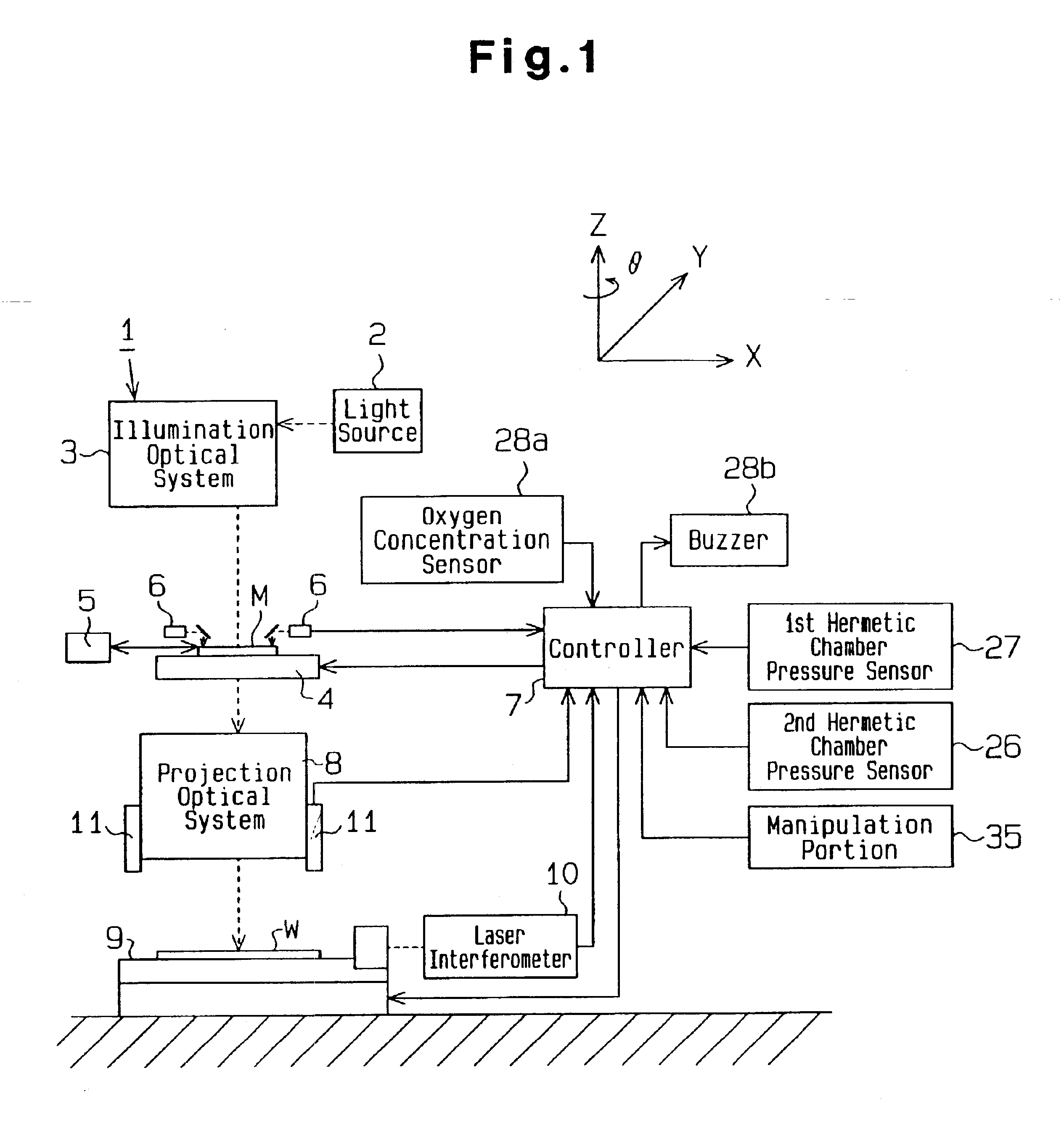
[0023]An exposure apparatus according to the present invention will now be discussed with reference to FIGS. 1 and 2. An exposure apparatus 1 shown in FIG. 1 is provided with a light source 2. The light source 2 is formed by an excimer laser, an Hg lamp, or the like, and emits ultraviolet rays or far ultraviolet rays into an illumination optical system 3.

[0024]Although not shown in the drawings, the illumination optical system 3 includes a collimator lens, a fly eye lens, and a reticle blind or dichroic mirror, and uses the ultraviolet rays or far ultraviolet rays emitted from the light source 2 as a uniform exposure light (irradiation light). The exposure light illuminates a mask M on a mask stage 4.

[0025]The mask M is held on the mask stage 4, which is movable along a two dimensional XY plane, by means of vacuum suction. A mask exchanging mechanism 5 holds a plurality of the masks M having different patterns and exchanges the masks with the mask M on the mask stage 4. A mask align...

second embodiment

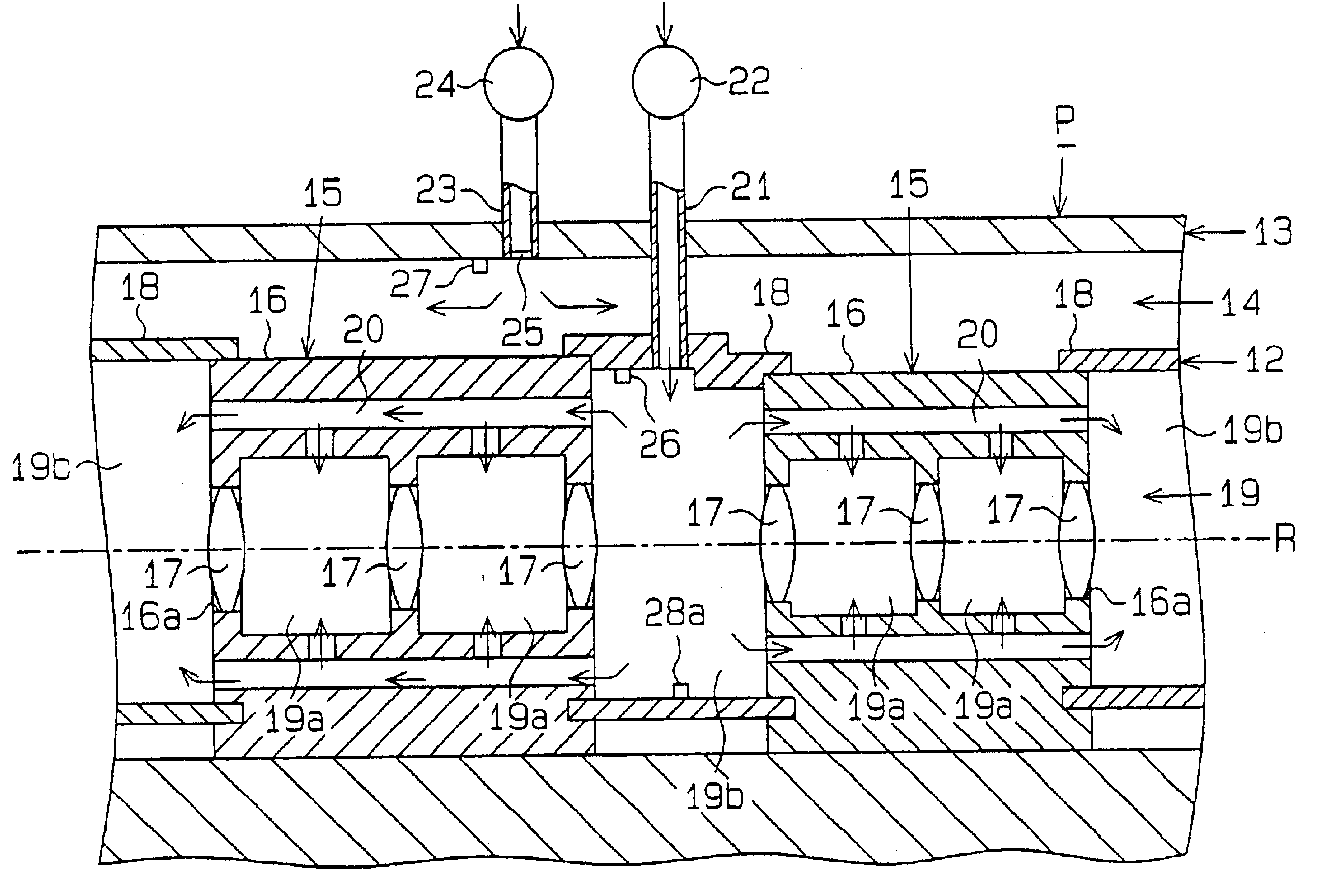
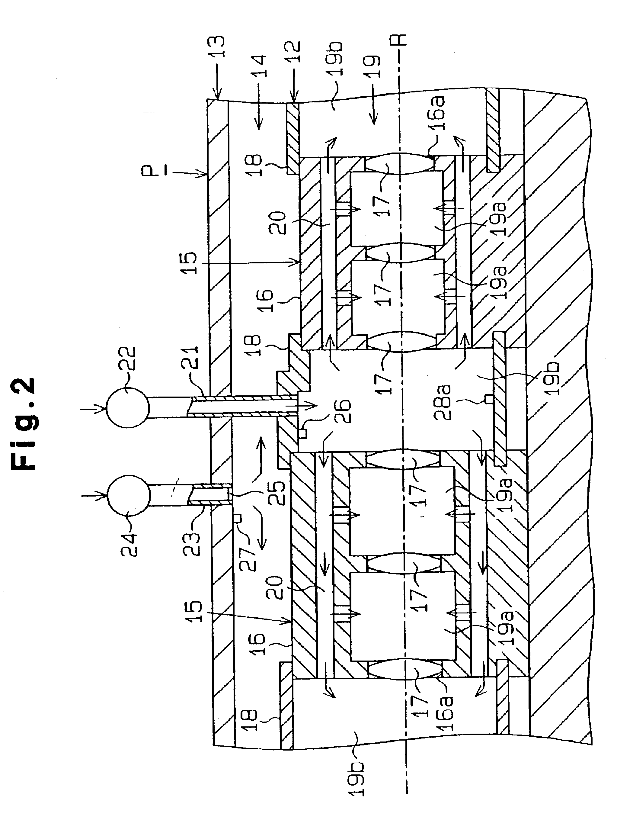
[0051]A second embodiment according to the present invention will now be described with reference to FIGS. 1 and 3. The apparatus of the second embodiment differs from the apparatus of the first embodiment in the points discussed below. Members of the first embodiment that are identical to those in the second embodiment are denoted with a reference numeral that is the same as the first embodiment and will not be described.

[0052]In the projection lens barrel 16 of each lens system 15, the passage 20 is separated from the sections 19b of the coupling tubes 18 adjacent to the projection lens barrel 16. Accordingly, the sections 19a between the lenses 17 in each of the projection lens barrels 16 are separated from the section 19b in each of the coupling tubes 18. The sections 19a, 19b each form hermetic chamber 19. The hermetic chamber 19 of each projection lens barrel 16 and the second hermetic chamber 19 of each coupling tube 18 are each provided with the first gas supply passage 21, ...

third embodiment

[0065]In the third embodiment, a pressure sensor 26 and an oxygen concentration sensor 28a are arranged in each illumination lens barrel 16.

[0066]In addition to advantages (1) to (7) of the first embodiment, the third embodiment has the advantages discussed below.

[0067]The shifting of the movable shielding cylinders 18a, 18b facilitates the switching of the optical members 34a in the optical device 31, maintains the hermetic seal of the closed space about the optical path R, and improves the function for protecting the illumination optical system 3. Further, this advantage is obtained with the illumination optical system 3 of the exposure apparatus 1.

[0068]In the present embodiment, the deterioration of the inner cover 12 is checked based on changes in the oxygen concentration of the second hermetic chamber 19. However, the deterioration of the inner cover 12 may also be checked based on changes in the relationship between the pressure sensors 26 and the gas supply portions 22. That...


PUM


Abstract

An optical apparatus having at least one optical element arranged along an optical path of an irradiation light. A first hermetic chamber is defined along the optical path separating the optical path from ambient air and charged with a predetermined gas. A second hermetic chamber is located in the first hermetic chamber separating the optical path from the gas in the first hermetic chamber and retaining the optical elements.

Description

RELATED APPLICATION[0001]This application is a continuation of U.S. application Ser. No. 09 / 675,728 filed on Sep. 29, 2000, now abandoned, which is a continuation of PCT application number PCT / JP99 / 01562 filed on Mar. 26, 1999. U.S. application Ser. No. 09 / 675,728 is hereby incorporated by reference herein.BACKGROUND OF THE INVENTION[0002]The present invention relates to an optical apparatus that retains an optical element. Further, the present invention relates to an exposure apparatus that employs an optical apparatus in an optical system, which illuminates a mask with an exposure light and uses the exposure light to transfer a pattern of the mask on a substrate.[0003]In a conventional exposure apparatus, in which an exposure light from a light source, such as an ArF excimer laser, is employed, the exposure of the exposure light to the oxygen in the air causes absorption of the exposure light by the oxygen and forms ozone. This is because the illumination spectral line of the expo...

Claims


Application Information

Patent Timeline
IPC IPC(8): G03F7/20
CPCG03F7/2041G03F7/70058G03F7/70808G03F7/70883G03F7/70933G03F7/70983G03F7/7015G03F7/70158G03F7/70341G03F7/70825
Inventor MURAYAMA, MASAYUKINAKAMURA, KYOJIOGATA, TAROMORI, SUSUMU
Owner NIKON CORP
Why Eureka
Try Eureka