Dynamic detector interlacing for computed tomography

a computed tomography and detector array technology, applied in the field of diagnostic imaging arts, can solve the problems of reducing the resolution in the under-sampled direction, reducing the sampling range, and generating image artifacts, so as to increase the sampling range, avoid aliasing and associated image artifacts, and increase the dynamic range

Inactive Publication Date: 2005-11-08
KONINKLIJKE PHILIPS ELECTRONICS NV
View PDF13 Cites 20 Cited by
  • Summary
  • Abstract
  • Description
  • Claims
  • Application Information

AI Technical Summary

Benefits of technology

[0012]One advantage of the present invention resides in increased sampling in the Z-direction.
[0013]Another advantage of the present invention resides in sampling in the Z-direction which satisfies the Nyquist criteria to avoid aliasing and associated image artifacts.
[0014]Yet another advantage of the present invention resides in combining detector element signals in the analog domain close to the detectors, which increases dynamic range and reduces image noise and dose requirements.
[0015]Still yet another advantage of the present invention resides in reducing the number of data acquisition and processing channels and the total volume of collected data, which results in reduced DAS complexity and cost.
[0016]Numerous additional advantages and benefits of the present invention will become apparent to those of ordinary skill in the art upon reading the following detailed description of the preferred embodiment.

Problems solved by technology

A problem arises in conventional CT imaging because the data is under-sampled.
The undersampling can produce image artifacts and reduced resolution in the under-sampled direction.
However, source wobbling is difficult to apply in the axial or Z-direction.
Again, this method is generally inapplicable for the axial direction.
However, these approaches increase the cost, complexity, and bandwidth of the data acquisition system and associated signal processing electronics.

Method used


Image

  • Dynamic detector interlacing for computed tomography
  • Dynamic detector interlacing for computed tomography
  • Dynamic detector interlacing for computed tomography

Examples


Embodiment Construction

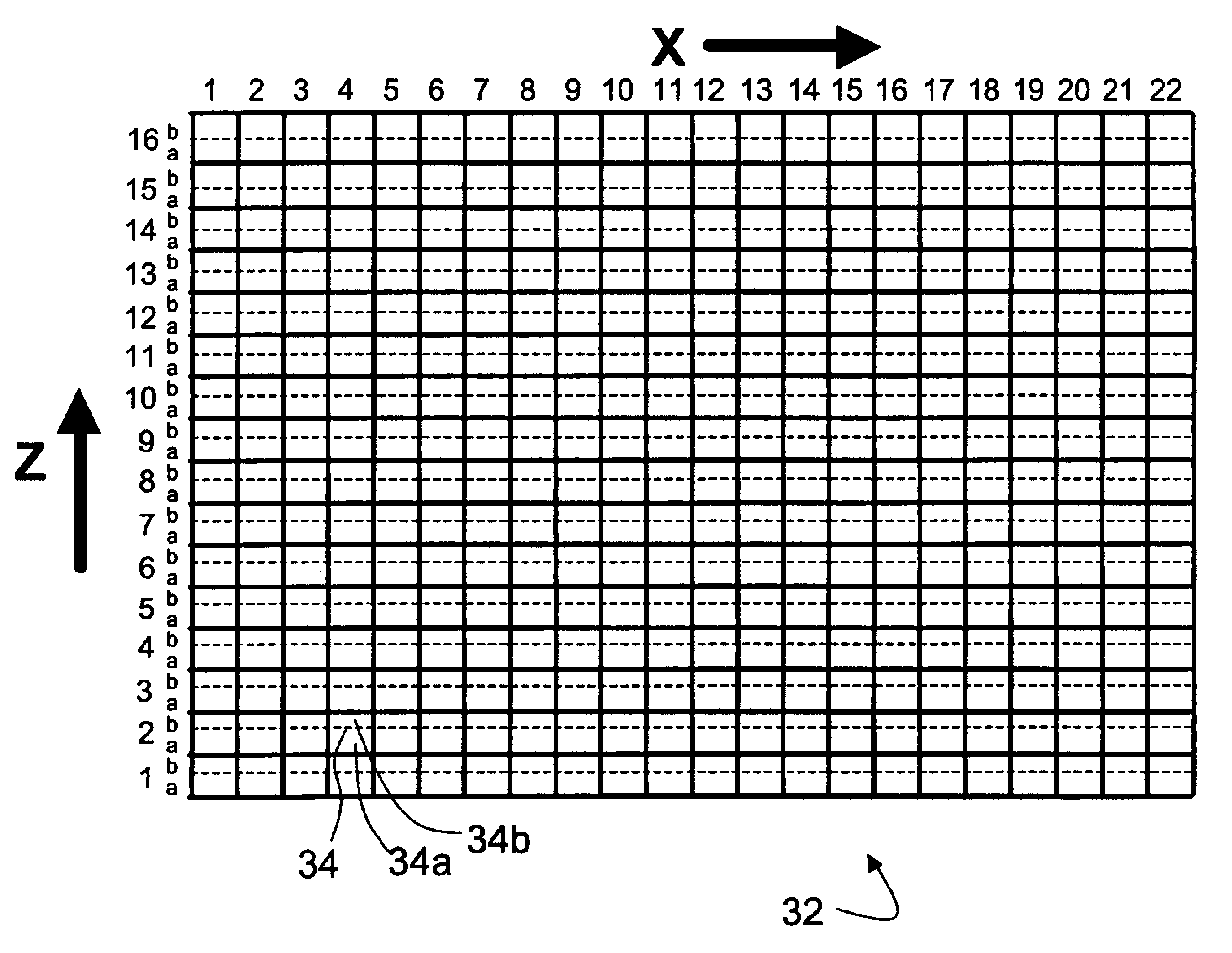
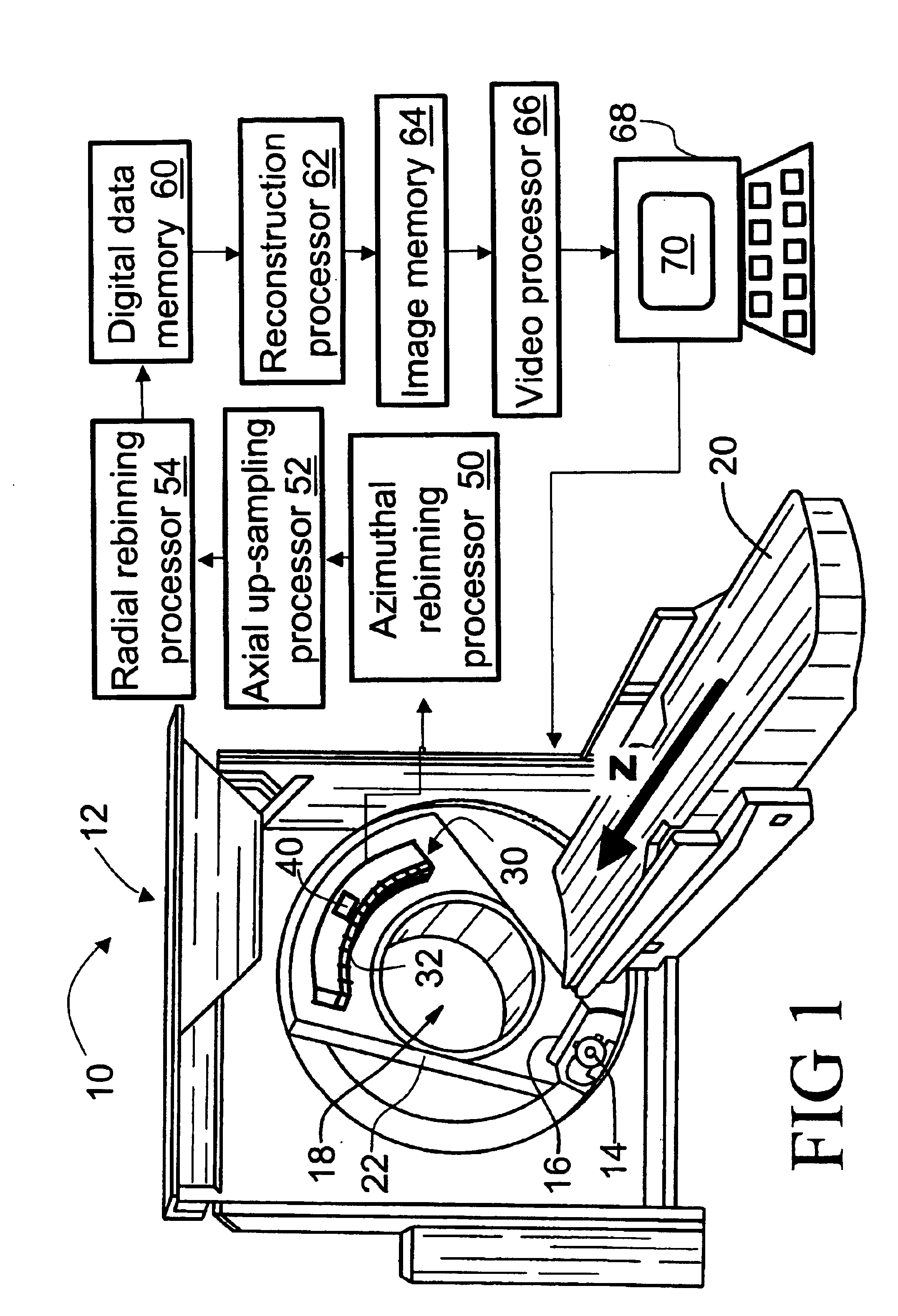
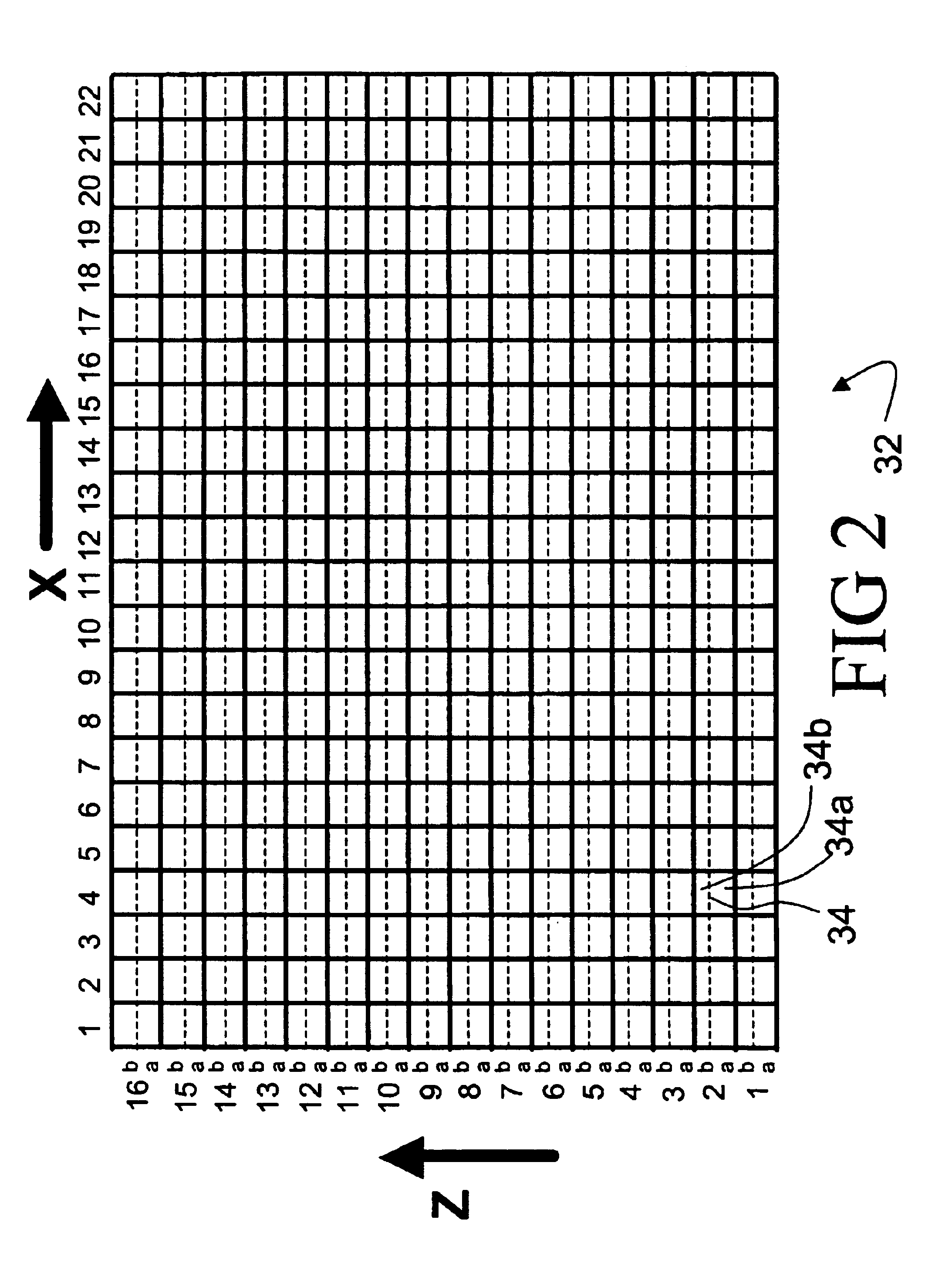
[0025]With reference to FIG. 1, a computed tomography (CT) imaging apparatus 10 includes a CT scanner 12 with an x-ray source 14 and a collimator 16 that cooperate to produce a cone-shaped, wedge-shaped, or otherwise-shaped x-ray beam directed into an examination region 18. A subject (not shown), such as a patient, is arranged on a subject support 20 and placed at least partially into the examination region 18. Preferably, the patient support 20 is linearly movable in an axial or Z-direction while the x-ray source 14 is rotatable on a rotating gantry 22.

[0026]In an exemplary helical imaging mode, the gantry 22 rotates simultaneously with linear axial advancement of the subject support 20 to effectuate a helical orbiting of the x-ray source 14 and collimator 16 about the examination region 18. However, other imaging modes can also be employed, such as a multi-slice imaging mode in which the gantry 22 rotates as the subject support 20 remains stationary to effectuate a circular orbiti...


PUM


Abstract

A data acquisition system (DAS) (30) for a computed tomography (CT) scanner (12) includes a two-dimensional array (32) of detectors (34) which is arranged to detect x-rays produced by the CT scanner (12). Each detector (34) is divided into two sub-detectors (34a, 34b) along an axial direction (z). A high-speed switching circuit (40) combines selected adjacent sub-detector outputs (34a, 34b), e.g. combining a sub-detector n alternately with sub-detectors (n−1) and (n+1). The high-speed switching circuit (40) switches its configuration between DAS measurements to produce interlaced DAS output signals along the axial direction (z).

Description

BACKGROUND OF THE INVENTION[0001]The present invention relates to the diagnostic imaging arts. It particularly relates to computed tomography imaging employing a two-dimensional detector array that enables rapid acquisition of volumetric imaging data, and will be described with particular reference thereto. However, the invention will also find application in other types of detector arrays for a variety of imaging applications employing x-rays, visible light, or other types of radiation.[0002]Computed tomography (CT) imaging typically employs an x-ray source that generates a fan-beam or cone-beam of x-rays that traverse an examination region. A subject arranged in the examination region interacts with and absorbs a portion of the traversing x-rays. A CT data acquisition system (DAS) including a two-dimensional detector array is arranged opposite the x-ray source to detect and measure intensities of the transmitted x-rays. Typically, the x-ray source and the DAS are mounted at opposi...

Claims


Application Information

Patent Timeline
Patent Type & Authority Patents(United States)
IPC IPC(8): A61B6/03
CPCA61B6/032A61B6/5205A61B6/4021A61B6/4085
Inventor BRUNNETT, CARL J.
Owner KONINKLIJKE PHILIPS ELECTRONICS NV
Why Eureka
Try Eureka