H-bridge circuit for generating a high-energy biphasic waveform in an external defibrillator using single SCR and IGBT switches in an integrated package

a biphasic waveform and circuit technology, applied in the field of circuits for generating biphasic waveforms in external defibrillators, can solve the problems of ventricular fibrillation, common and life-threatening medical conditions, and the output circuit of implantable defibrillators is not adaptable for use in external defibrillators, and achieves sufficient current conducting capability, high energy discharge, and low energy

Inactive Publication Date: 2005-11-08
PHYSIO CONTROL INC
View PDF56 Cites 107 Cited by
  • Summary
  • Abstract
  • Description
  • Claims
  • Application Information

AI Technical Summary

Benefits of technology

[0016]Moreover, in addition to being able to conduct a high energy defibrillation pulse of 200 to 360 joules, the H-bridge output circuit is also capable of conducting a low energy defibrillation pulse for internal applications with an energy as low as 1 to 50 joules. Low energy defibrillation pulses are required when, for example, internal paddles are coupled to the defibrillator for use in surgery to directly defibrillate the heart, or for pediatric defibrillation, or for cardioversion of some arrhythmias in both pediatrics and adults. To allow the delivery of a low energy defibrillation pulse, in one embodiment the output circuit switches in one or more of the legs are driven by gate drive circuits which provide a repetitively pulsed control signal to the gates of the switches. The pulsed control signal on the gates allows the high voltage switches to remain conducting even when conducting very low currents.
[0017]In accordance with another aspect of the invention, a gate drive circuit biases on the IGBT in the fourth leg with a sufficient voltage over a short interval to allow the leg to conduct a high current without being damaged. In one embodiment, the leg can conduct a current of at least approximately 200 amps, while in another embodiment a current of at least approximately 400 amps can be conducted. Biasing the IGBTs in this manner allows the IGBTs to withstand a high energy discharge such as occurs when a low resistance load is placed at the output of the circuit.
[0018]In accordance with still another aspect of the invention, all of the output circuit switches are selected to have sufficient current conducting capability to allow the switches in two of the legs on the same side of the H-bridge to provide a shorted path for the discharge of unwanted energy from the energy storage capacitor. The use of two legs on one side of the H-bridge to discharge the capacitor eliminates the need for an additional discharge circuit to perform this internal energy dump function. In addition, the H-bridge circuit is able to perform the internal energy dump quickly and accurately using advantageous component values that would not be practical to implement in a separat

Problems solved by technology

One of the most common and life-threatening medical conditions is ventricular fibrillation, a condition where the human heart is unable to pump the volume of blood required by the human body.
Because implantable defibrillators only apply a low energy defibrillation pulse having a maximum energy of approximately 35 joules, however, the output circuit in implantable defibrillators is not adaptable for use in the external defibrillator.
A 200 joule energy pulse applied to an implantable defibrillator bridge circuit would overload the bridge circuit components and cause the circuit to fail.
Because of the small energies used for pacing pulses, the circuitry used to generate

Method used


Image

  • H-bridge circuit for generating a high-energy biphasic waveform in an external defibrillator using single SCR and IGBT switches in an integrated package
  • H-bridge circuit for generating a high-energy biphasic waveform in an external defibrillator using single SCR and IGBT switches in an integrated package
  • H-bridge circuit for generating a high-energy biphasic waveform in an external defibrillator using single SCR and IGBT switches in an integrated package

Examples


Embodiment Construction

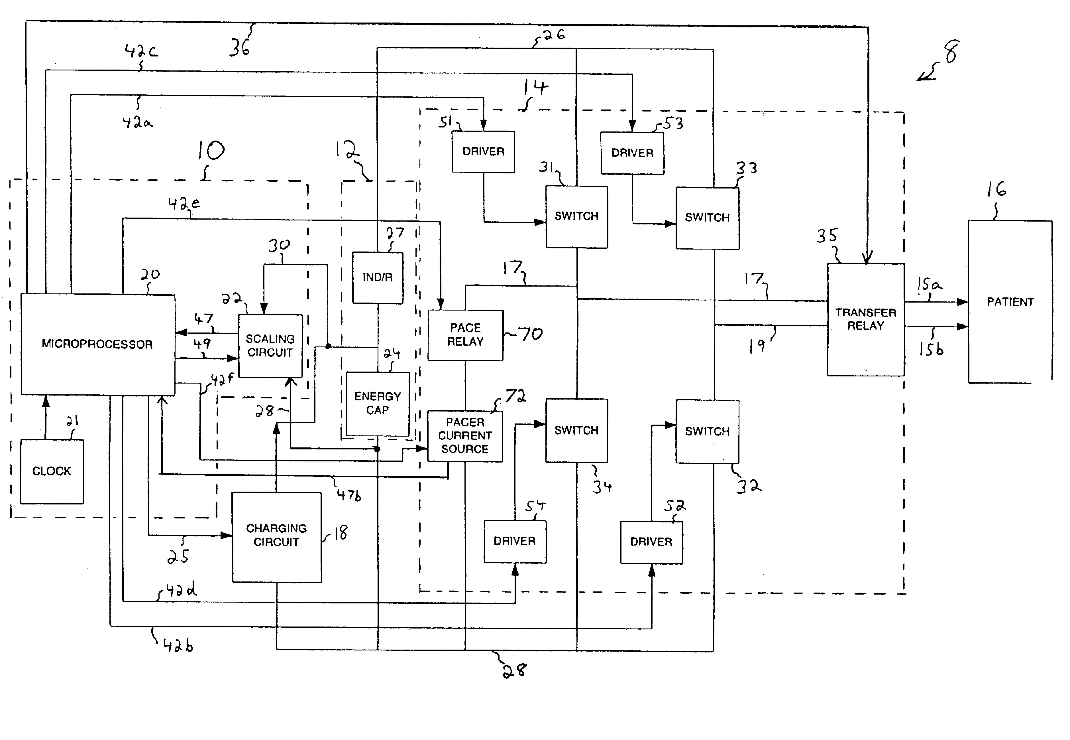
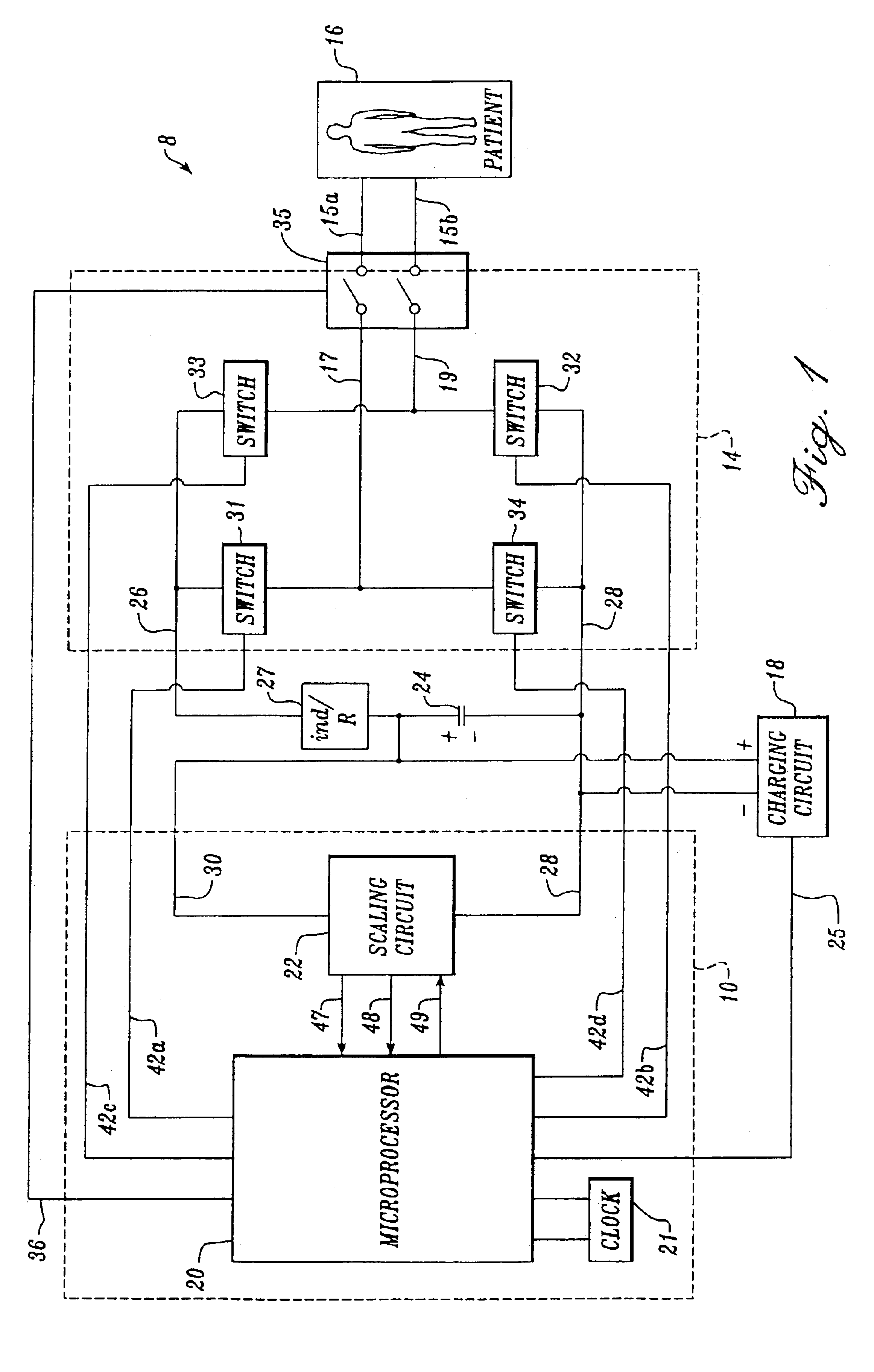
[0040]FIG. 1 is a block diagram of an external defibrillator 8 that is connected to a patient 16. The defibrillator includes a microprocessor 20 that is connected to an energy storage capacitor 24 via a charging circuit 18. During the operation of the defibrillator, the microprocessor controls the charging circuit 18 by a signal on a control line 25 to charge the energy storage capacitor to a desired voltage level. To monitor the charging process, the microprocessor is connected to a scaling circuit 22 by a pair of measurement lines 47 and 48, and by a control line 49. The scaling circuit 22 is connected to the energy storage capacitor 24 by a bridge line 28, which connects to the negative lead of the capacitor, and by a line 30, which connects to the positive lead of the capacitor. A clock 21 is also connected to the microprocessor 20.

[0041]The scaling circuit 22 is used to step down the voltage across the energy storage capacitor 24 to a range that may be monitored by the micropro...


PUM


Abstract

An external defibrillator with an output circuit having four legs arrayed in the form of an “H” (an “H-bridge”) is disclosed. The output circuit is designed to be able to conduct a range of defibrillation pulse energies, from below 50 joules to above 200 joules. Each leg of the output circuit contains a solid-state switch. By selectively switching on pairs of switches in the H-bridge, a biphasic defibrillation pulse may be applied to a patient. The switches in three of the legs of the H-bridge output circuit are preferably SCR switches, while the fourth leg includes an IGBT switch. In one embodiment, a single power switch is utilized in each of the legs of the H-bridge output circuit, and are included in a single integrated module or package. The use of single semiconductor switches in an integrated surface mountable module or package simplifies the assembly and manufacturing of the defibrillator device. The use of a single IGBT in a leg of the H-bridge (as opposed to two or more IGBTs in series) also greatly simplifies the drive circuitry required to turn on and off the IGBT.

Description

CROSS-REFERENCES TO RELATED APPLICATIONS[0001]This application is a continuation-in-part of prior application Ser. No. 09 / 706,578, filed Nov. 3, 2000 now U.S. Pat. No. 6,477,413, which is a continuation of prior application Ser. No. 09 / 287,483, filed Apr. 6, 1999, now U.S. Pat. No. 6,175,765, which is a continuation-in-part of prior application Ser. No. 09 / 035,690, filed Mar. 5, 1998, now U.S. Pat. No. 6,041,254, which is a continuation-in-part of prior application Ser. No. 08 / 811,833, filed Mar. 5, 1997, now U.S. Pat. No. 5,824,017, priority from the filing dates of which is hereby claimed under 35 U.S.C. § 120.FIELD OF THE INVENTION[0002]This invention relates generally to apparatus for generating defibrillation waveforms, and more particularly to a circuit for generating a biphasic defibrillation waveform in an external defibrillator.BACKGROUND OF THE INVENTION[0003]One of the most common and life-threatening medical conditions is ventricular fibrillation, a condition where the h...

Claims


Application Information

Patent Timeline
IPC IPC(8): A61N1/39
CPCA61N1/39A61N1/3912A61N1/3904
Inventor WALTMAN, BARRY F.SULLIVAN, JOSEPH L.BORSCHOWA, LAWRENCE A.NOVA, RICHARD C.
Owner PHYSIO CONTROL INC
Why Eureka
Try Eureka