
Technique for analyzing arrayed signals using quantum expressor functions

a quantum expressor and arrayed signal technology, applied in the field of biological samples analysis, can solve the problems of poor repeatability, high cost, and high cost, and achieve the effect of greatly enhancing the reliability of the dot spectrogram analysis, and reducing the cost of performing the analysis

Inactive Publication Date: 2005-11-08
VIALOGY
View PDF6 Cites 18 Cited by
  • Summary
  • Abstract
  • Description
  • Claims
  • Application Information

AI Technical Summary

Benefits of technology

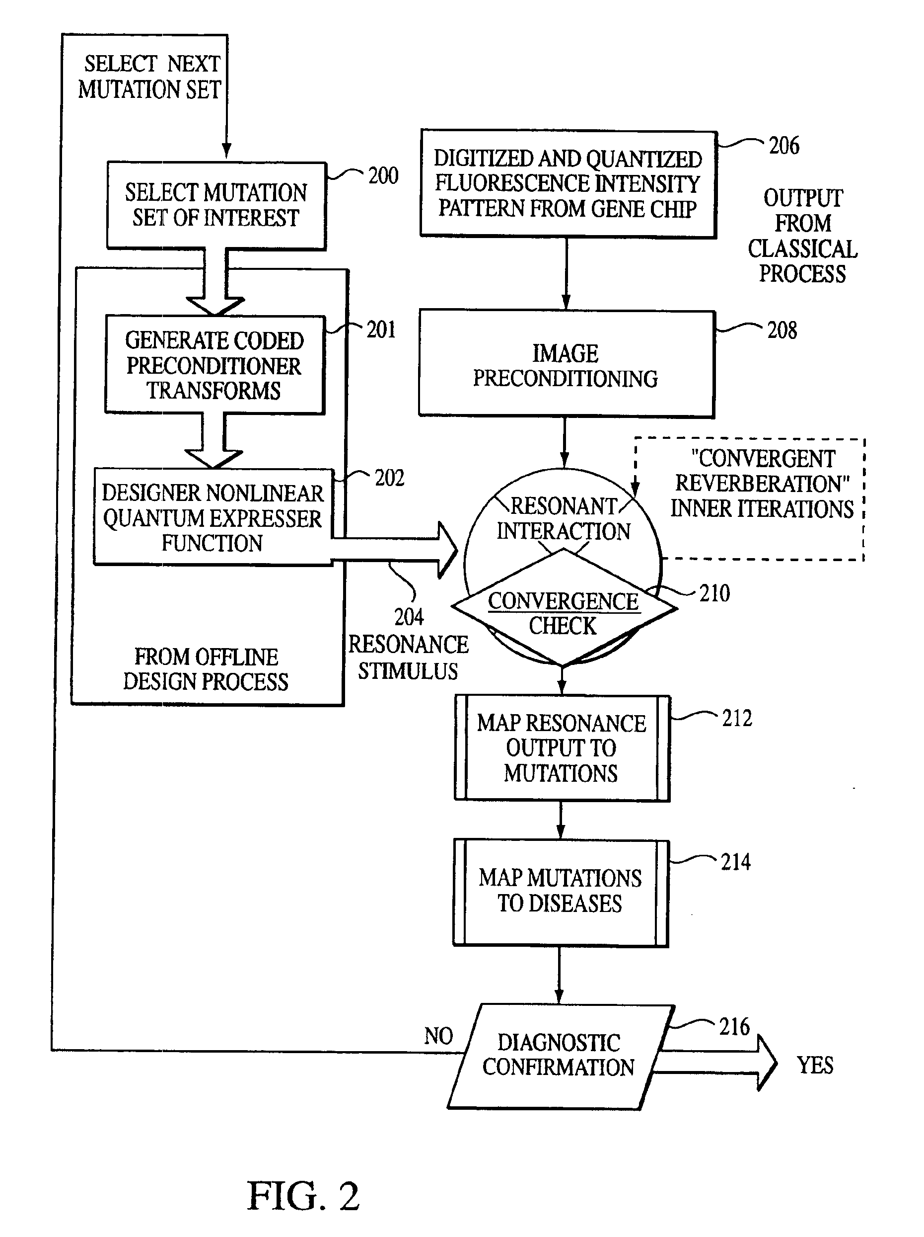
[0019]By exploiting a resonant interaction, mutation signatures may be identified within a dot spectrogram even in circumstances involving low signal to noise ratios or, in some cases, negative signal to noise ratios. By permitting the mutation signatures to be identified in such circumst...

Problems solved by technology

Unfortunately, under conventional techniques, the step of analyzing the fluorescent pattern to determine the nature of any conditions characterized by the DNA is expensive, time consuming, and somewhat unreliable for all but a few particular conditions or diseases.
One major problem with many conventional techniques is that the techniques have poor repeatability.
Also, skilled technicians are required to prepare DNA samples, implement the hybridization protocol, and analyze the DNA microarray output possibly resulting in high costs.
One reason that repeatability is poor is that the signatures within the digitized hybridization pattern (also known as a “dot spectrogram”) that are representative of mutations of interest are typically very weak and are immersed in considerable noise.
Conventional techniques are not particularly effective in extracting mutation signatures from dot spectrograms in low signal to noise circumstances.

Method used


Image

  • Technique for analyzing arrayed signals using quantum expressor functions
  • Technique for analyzing arrayed signals using quantum expressor functions
  • Technique for analyzing arrayed signals using quantum expressor functions

Examples


Embodiment Construction

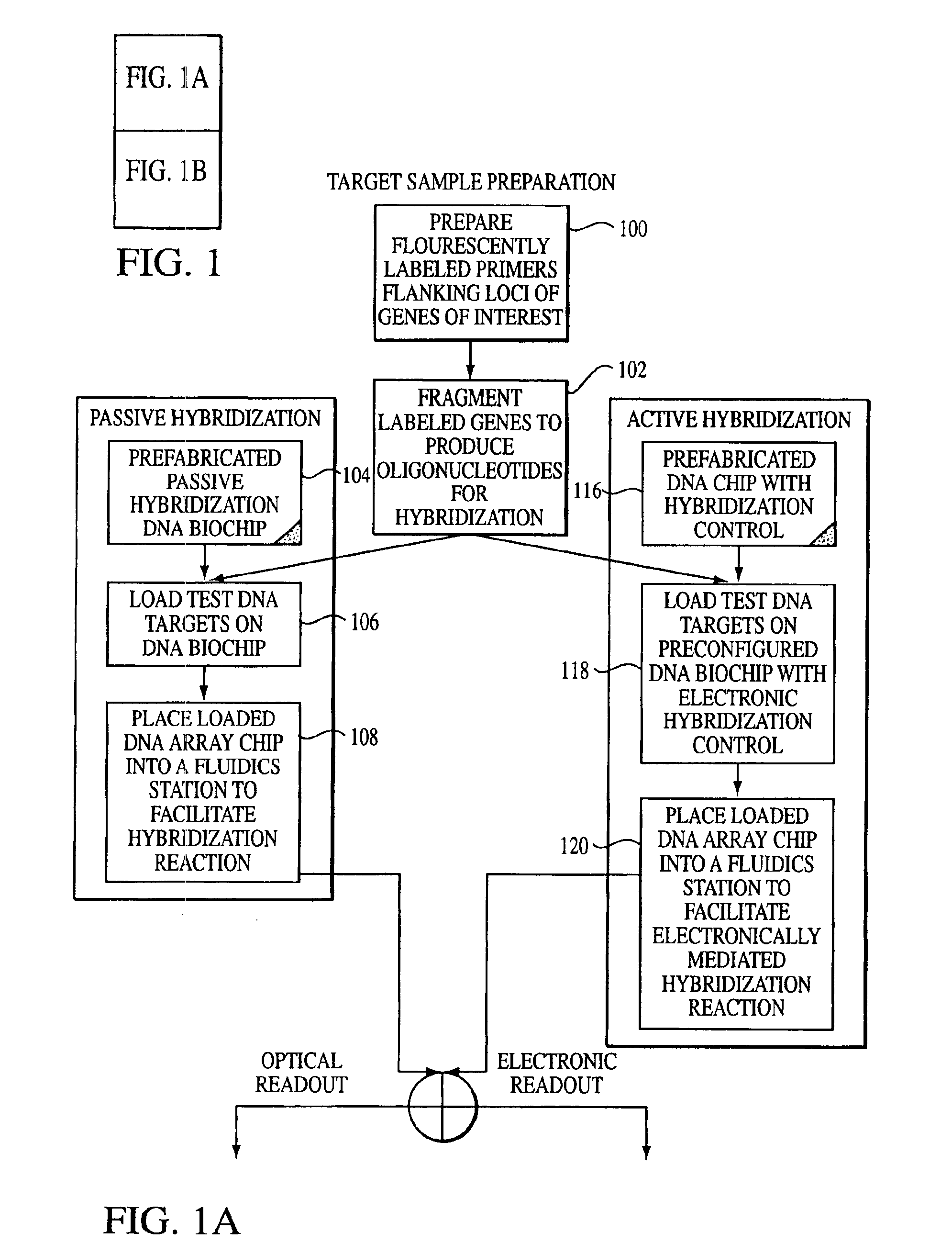
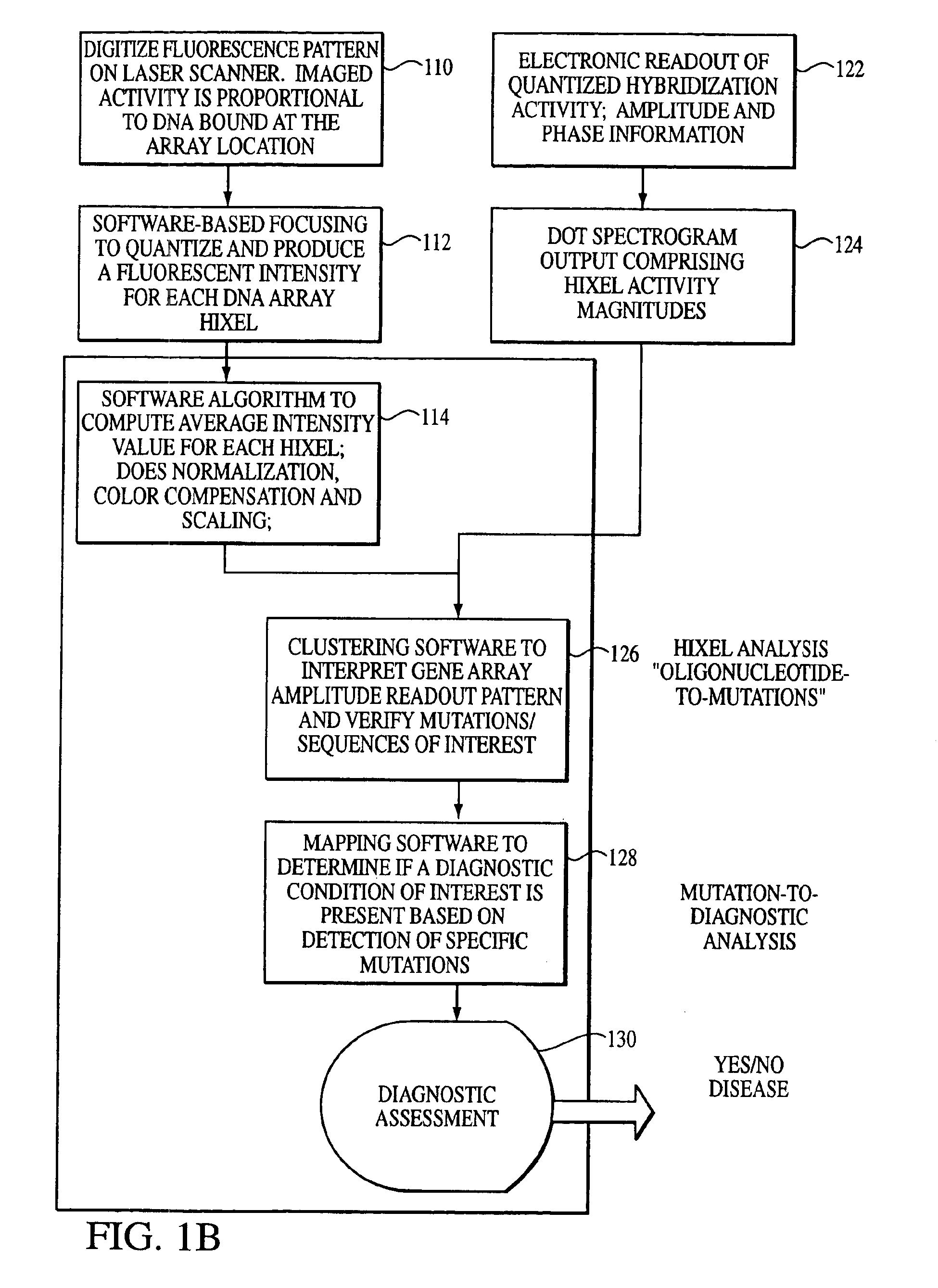
[0029]With reference to the remaining figures, exemplary embodiments of the invention will now be described. The invention will be described primarily with respect to an exemplary method for analyzing mutations signatures within output patterns of hybridized microarrays generated using DNA samples, but principles of the invention apply to the analysis of other protein-based samples or to other types of output patterns as well.

[0030]Overview

[0031]Briefly, the exemplary method exploits, among other features: (a) a novel representation, interpretation and mathematical model for the immobilized oligonucleotide hybridization patterns, represented via a dot spectrogram; (b) a new “active” biomolecular target detection and discrimination method based on quantum resonance interferometry, and (c) a new spatial hashing function that yields accurate diagnostic assessment.

[0032]To this end, the exemplary method exploits a fundamentally different computational paradigm for mutation expression de...


PUM


Abstract

A technique for determining events of interest within an output pattern generated from a detected image of an array of detectors where the output pattern comprises signals associated with noise, and signals associated with the events of interest which have intensities both greater and less than intensities of signals associated with noise. Quantum resonance interferometry is utilized to amplify signals associated with the events of interest having an intensity lower than the intensity of signals associated with noise, to an intensity greater than the intensity of the signals associated with noise to generate a modified output pattern. Once the desired signals are amplified, the technique determines which signals within the modified output pattern correlate with events of interest thus permitting a determination to be made whether a certain event of interest has occurred.

Description

CLAIM OF PRIORITY[0001]This application is a continuation of U.S. patent application Ser. No. 09 / 913,132, filed Aug. 9, 2001, now U.S. Pat. No. 6,671,625, which is a national stage application of PCT US00 / 04076 filed on Feb. 17, 2000, which is a continuation of and claims priority to U.S. patent application Ser. No. 09 / 253,789, filed on Feb. 22, 1999 now U.S. Pat. No. 6,136,541.FIELD OF THE INVENTION[0002]The invention generally relates to techniques for analyzing biological samples such as DNA, RNA, or protein samples and in particular to techniques for analyzing the output patterns of hybridized biochip microarrays.BACKGROUND OF THE INVENTION[0003]A variety of techniques have been developed to analyze DNA or other biological samples to identify diseases, mutations, or other conditions present within a patient providing the sample. Such techniques may determine, for example, whether the patient has any particular disease such as cancer or AIDS, or has a predisposition toward the di...

Claims


Application Information

Patent Timeline
IPC IPC(8): G06F19/00G16B25/10G16B40/10
CPCB82Y5/00B82Y10/00G06F19/20G06F19/24G16B25/00G16B40/00G16B40/10G16B25/10
Inventor GULATI, SANDEEP
Owner VIALOGY
Learn More