
Common-mode choke coil

a choke coil and common-mode technology, applied in the direction of transformer/inductance magnetic cores, cores/yokes, inductances, etc., can solve the problems of inability to satisfy eop and eye pattern, inability to eliminate high-frequency common-mode noise in the interface usb 2.0 ranging from several hundred mhz to several ghz, and inability to secure eliminating characteristics

Inactive Publication Date: 2005-11-15
MURATA MFG CO LTD
View PDF14 Cites 45 Cited by
  • Summary
  • Abstract
  • Description
  • Claims
  • Application Information

AI Technical Summary

Benefits of technology

[0011]In order to solve the problems of the conventional techniques described above, preferred embodiments of the present invention provide a common-mode choke coil which is capable of achieving a desired impedance value while having a small amount of deviation of the impedance value.
[0013]By such a configuration, the magnetic shield has a relative magnetic permeability that is smaller than that of the core, so that the effective magnetic permeability of the entire coil can be reduced in comparison with that of the conventional coil in that a flat plate core having the same relative magnetic permeability as that of the core is arranged between two flanges. Therefore, by combining features of preferred embodiments of the present invention with the conventional coil, the degree of freedom of the impedance values of the coil is greatly increased, thereby setting the impedance to be a desired value, so that noise can be reliably eliminated from a transmission line. Also, because there is provided the magnetic shield with a relative magnetic permeability that is smaller than that of the core, even when changes in the shape and arrangement of the magnetic shield are produced, the impedance value can be set at a high degree of accuracy reducing deviation therein, while the yield can be improved. Furthermore, because the magnetic shield having the relative magnetic permeability that is smaller than that of the core is provided, a common-mode impedance value can be increased for a high frequency of about 100 MHz or more, for example, in comparison with when the flat-plate core having the same relative magnetic permeability as that of the core is formed according to the conventional technique, so that common-mode impedance characteristics can be improved.
[0017]Thereby, the magnetic powder-containing resin coating adheres to the core having the wire wound therearound so as to be firmly fixed thereon, thereby simplifying the manufacturing process so as to increase the productivity. Also, by adjusting the content of the magnetic powder, the relative magnetic permeability of the magnetic powder-containing resin coating can be changed, so that various impedance values can be easily set. Moreover, since the magnetic shield is made of the magnetic powder-containing resin coating, the height of the entire common-mode choke coil can be reduced to be smaller in comparison with when the flat-plate core is formed using the conventional technique. Also, the magnetic powder-containing resin coating adheres to the core having the wire wound therearound, so that the wire may be protected with the magnetic powder-containing resin coating while the wire is fixed so as to reduce the amount of deviation in the impedance value, thereby stabilizing the impedance value.
[0019]Thereby, the resin coating adheres to the core having the wire wound therearound so as to be firmly fixed thereon, simplifying the manufacturing process. Also, since the magnetic shield is made of the resin coating, the height of the entire common-mode choke coil can be reduced to be smaller in comparison with when the flat-plate core is formed according to the conventional technique. Furthermore, the resin coating adheres to the core having the wire wound therearound, so that the wire may be protected with the resin coating while the wire is fixed so as to reduce the amount of deviation in the impedance value, stabilizing the impedance value. Also, since the magnetic shield is made of the resin coating with a relative magnetic permeability of approximately 1, a common-mode impedance value can be increased for a high frequency of 100 MHz or more, for example, in comparison with when the flat-plate core having the same relative magnetic permeability as that of the core is provided as in the conventional technique, so that common-mode impedance characteristics can be improved.

Problems solved by technology

However, because the applicable frequencies of a conventional common-mode choke coil are about several MHz to about 200 MHz, high-frequency common-mode noise in the interface USB 2.0 ranging from several hundred MHz to several GHz cannot be eliminated.
At this time, there has been a problem that the EOP and the eye pattern cannot be satisfied at 120 Ω while noise eliminating characteristics cannot be secured at 67 Ω.
Also, in a structure in which a magnetic shielding member having substantially the same permeability as that of the magnetic core is connected between the flanges of the magnetic core, the impedance value may change because of variations in the clearance size between the magnetic core and the magnetic shielding member or the displacement of the magnetic shielding member, so that there has also been a problem that the EPO and eye pattern are not satisfied.

Method used


Image

  • Common-mode choke coil
  • Common-mode choke coil
  • Common-mode choke coil

Examples


Embodiment Construction

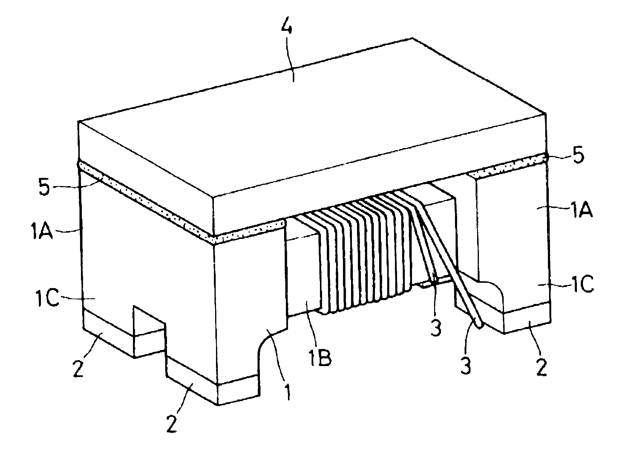
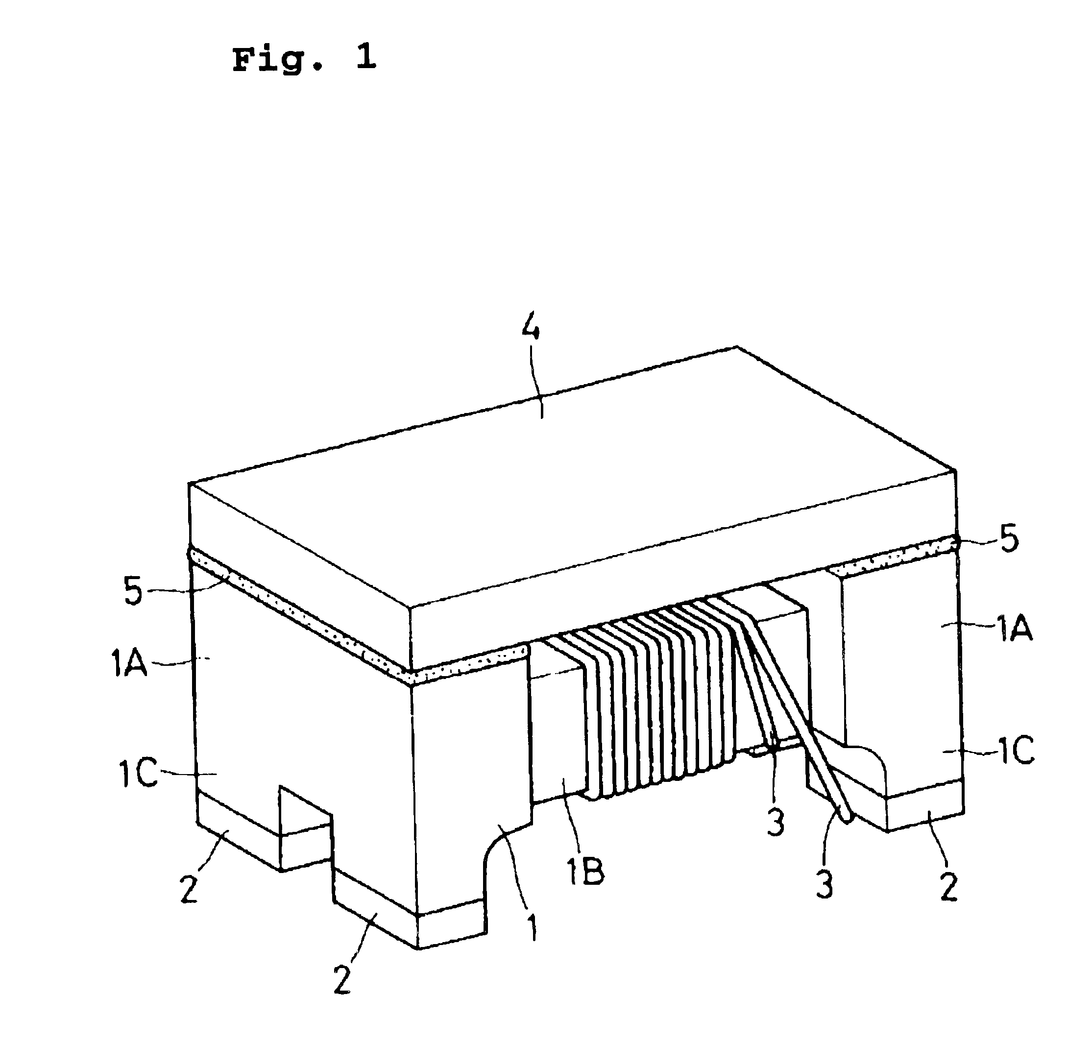
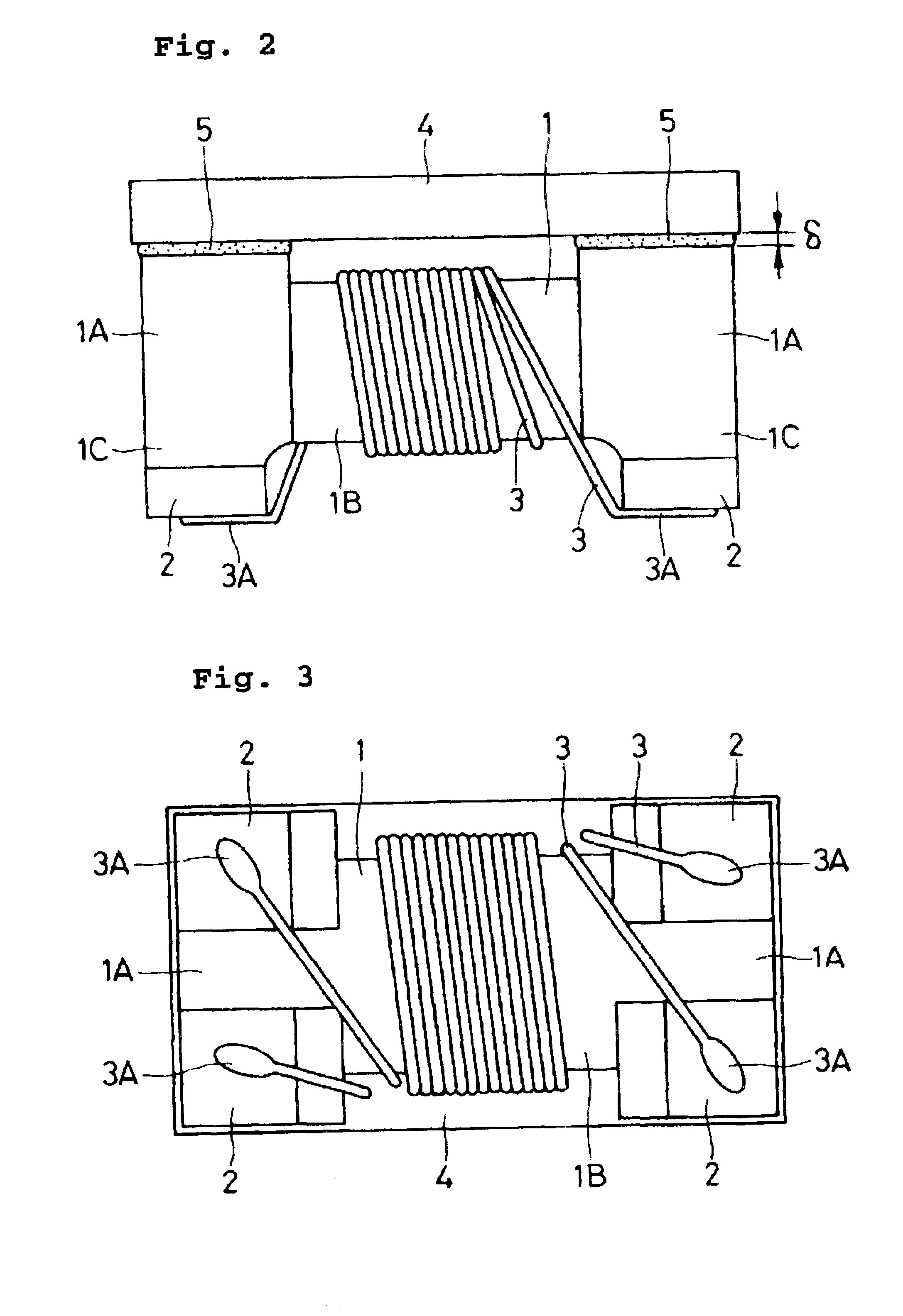
[0031]Preferred embodiments of a common-mode choke coil according to the present invention will be described in detail below with reference to the attached drawings.

[0032]FIGS. 1 to 3 show a first preferred embodiment, and a substantially prism-shaped core 1 includes large-diameter flanges 1A arranged at both ends and a small-diameter winding section 1B disposed between the two flanges 1A. The core 1 is preferably made of a magnetic material such as ferrite, and preferably has a relative magnetic permeability of about 200 μc to about 500 μc. In the bottom portion of each of the flanges 1A, a leg 1C which is forked into two parts is provided, and a curved notch is disposed between each of the legs 1C and the winding section 1B.

[0033]An electrode 2 disposed at the bottom portion of each leg 1C is preferably provided by forming electrode layers of nickel and tin with soldering on a base-electrode layer, which is formed by applying and sintering conductive paste such as silver and coppe...


PUM

PropertyMeasurementUnit
frequencyaaaaaaaaaa
frequenciesaaaaaaaaaa

Abstract

A common-mode choke coil includes a core having flanges disposed at both ends and a winding section arranged between the flanges. Electrodes are disposed in the flanges, while two pieces of wire are wound around the winding section and ends of the pieces of wire are connected to the electrodes. A ferrite plate with a relative magnetic permeability that is smaller than that of the core is attached on the upper surface of the flanges with an adhesive so as to cover the wire.

Description

BACKGROUND OF THE INVENTION[0001]1. Field of the Invention[0002]The present invention relates to a common-mode choke coil having a core and wire, and in particular, relates to a common-mode choke coil suitable for use in a common-mode filter for eliminating noise.[0003]2. Description of the Related Art[0004]In general, a wire-wound common-mode choke coil is known as a necessary radiant noise relief measure in a power supply line or as a common-mode noise relief measure of a high-frequency signal (Japanese Unexamined Patent Application Publication No. 2000-133522, for example). Such a common-mode choke coil utilizing a conventional technique includes a ferrite magnetic core with a winding core having flanges at both ends, a plurality of pieces of wire made of insulating coated-copper wire and wound around the winding core by several turns to several dozen turns in a bifilar winding manner, a magnetic shielding member (flat-plate core) connected between both the flanges of the magneti...

Claims


Application Information

Patent Timeline
Patent Type & Authority Patents(United States)
IPC IPC(8): H01F27/34H01F27/36H01F17/04H03H1/00H01F27/29H01F3/00H01F3/10H01F3/12H01F1/37
CPCH01F17/045H01F27/365H01F3/10H01F3/12H01F27/292H01F27/36H01F27/366
Inventor TOI, TAKAOMIHANATO, YOSHIOYAMADA, TATSUYUKI
Owner MURATA MFG CO LTD
Learn More