Head suspension configured for improved thermal performance during solder ball bonding to head slider

a head suspension and slider technology, applied in the direction of maintaining the head carrier alignment, recording information storage, instruments, etc., can solve the problems of distortion or damage to the head suspension components, and achieve the effect of reducing the mechanical and thermal effects of the solder ball bonding process

Inactive Publication Date: 2005-11-15
HUTCHINSON TECH
View PDF9 Cites 40 Cited by
  • Summary
  • Abstract
  • Description
  • Claims
  • Application Information

AI Technical Summary

Benefits of technology

[0006]The present invention provides a head suspension or head suspension component configured for solder ball bonding of a head slider to electrical traces on the head suspension or head suspension component. The head suspension or head suspension component includes electrical traces formed from electrically conductive material with the electrical traces having a bonding region adapted for electrical bonding to a head slider. Also included is a support structure providing support for at least portions of the electrical traces and having a head slider mounting region adapted to receive the head slider. The support structure is configured to mechanically and thermally isolate the bonding region of the electrical traces from the head slider mounting region to reduce the mechanical and thermal effects of a solder ball bonding process on the head suspension or head suspension component during solder ball bonding of the head slider to the electrical traces.
[0008]In yet another embodiment, the support structure includes a U-shaped slit formed around the bonding region so that the electrical traces of the bonding region are positioned on at least one support structure tongue. The support structure material of the tongue may be reduced to provide more of a cantilevered bonding region. In addition, the conductive material of the bonding region may be increased relative to conventional bonding regions so as to dissipate more heat during the bonding process.

Problems solved by technology

However, contact of the tool to the head suspension may cause distortion in or damage to the head suspension components.
However, shrinkage of the solder ball may cause distortion in the head suspension components at or near the bonding region, which may then affect head suspension characteristics, such as static attitude.

Method used


Image

  • Head suspension configured for improved thermal performance during solder ball bonding to head slider
  • Head suspension configured for improved thermal performance during solder ball bonding to head slider
  • Head suspension configured for improved thermal performance during solder ball bonding to head slider

Examples


first embodiment

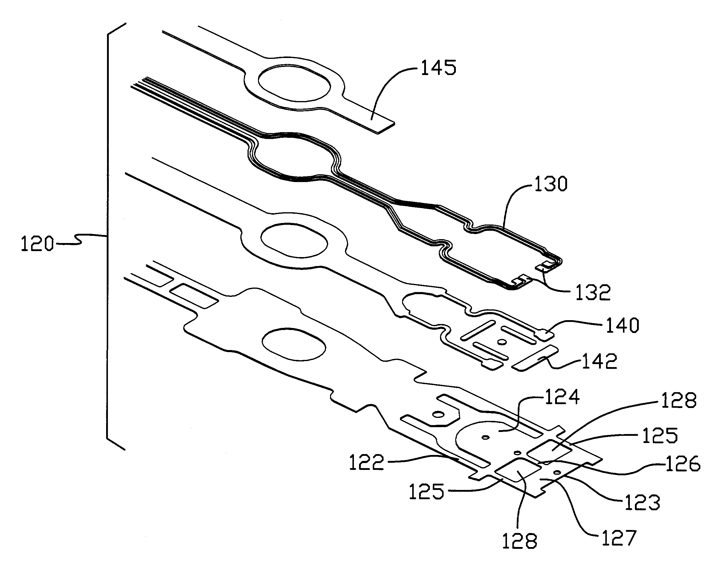
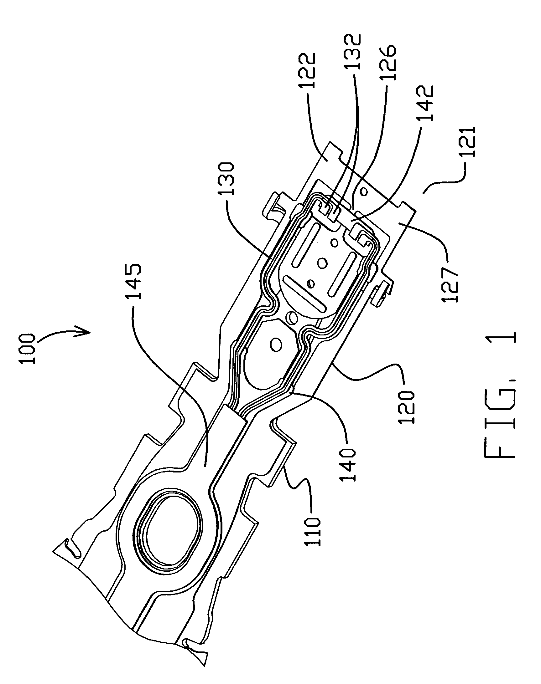
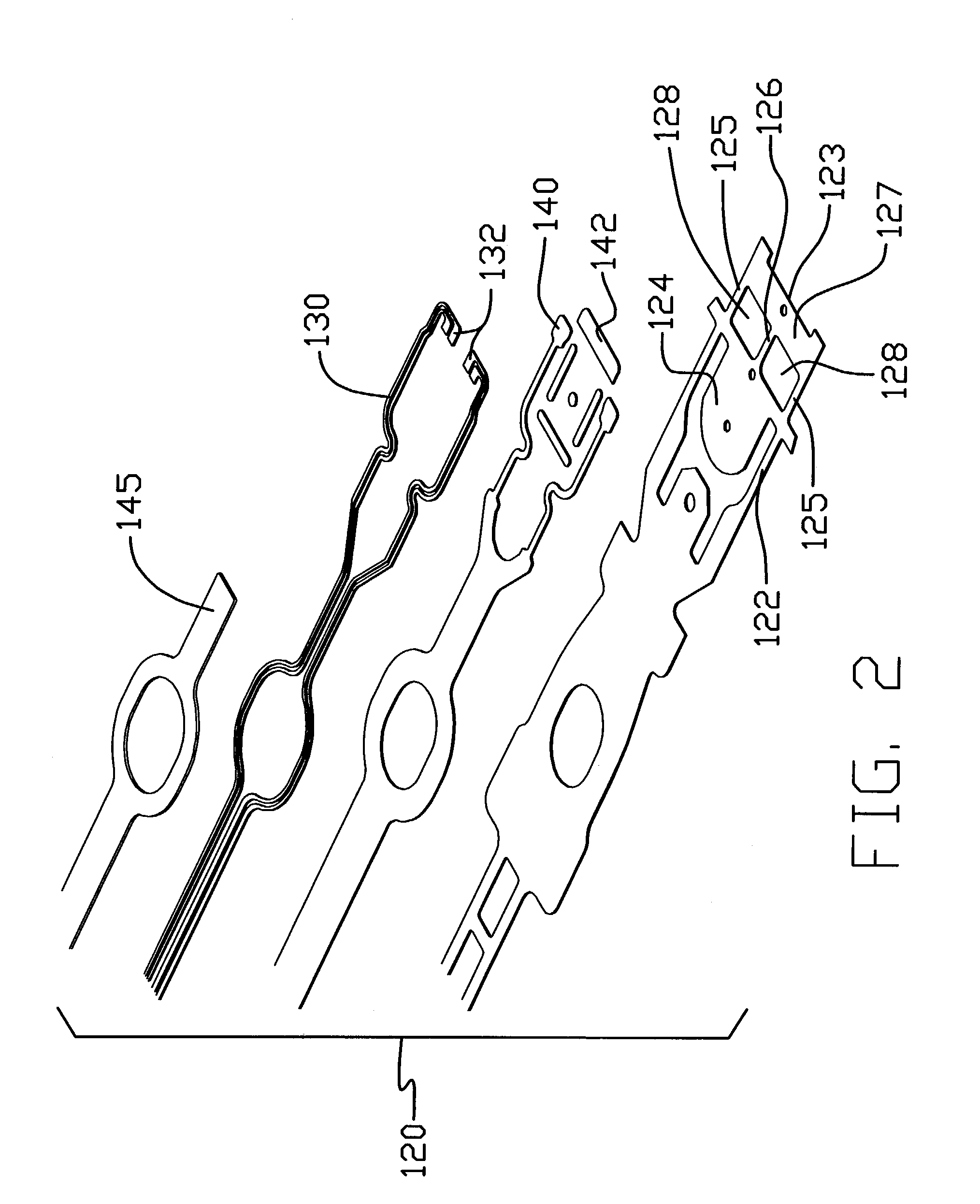
[0022]Referring to FIGS. 1–3, a portion of a head suspension 100 in accordance with the present invention is shown including a load beam 110 and a flexure 120. The flexure 120 includes integrated electrical leads or traces 130 that are preferably formed of copper and / or other electrically conductive material, a dielectric layer 140 and a stainless steel 122 or other resilient material layer. The dielectric layer 140 and stainless steel 122 together providing a support structure for the traces 130 and head slider 105. In addition, a cover layer 145 over the copper traces 130 may also be provided, if desired. The flexure 120 includes at a distal end 121 a head slider mounting region 124 to which a head slider 105 (shown in FIG. 3) is mounted. The head slider 105 includes head slider bonding pads 106 at one end that align with trace bonding pads 132 provided in the traces 130 on the flexure 120. Solder balls 134 are then applied at the juncture of the two types of bonding pads so as to...

second embodiment

[0027]Referring now to FIG. 6, a head suspension 300 in accordance with the present invention is shown having a flexure 310, including a head slider mounting region 314 and traces 320. A support structure includes a dielectric layer 330 and a stainless steel layer 312 configured in a similar manner to the stainless steel layer 122 of flexure 120, having a head slider mounting region 314 and a distal portion 313 including a cross beam 317 at a distal end 311. The cross beam 317 connects to the head slider mounting region 314 at a center longitudinal member 316 and two side longitudinal members 315, such that two apertures 318 are formed between the head slider mounting region 314 and the cross beam 317. A dielectric member 332 that extends across center longitudinal member 316 over apertures 318 provides support for trace bonding pads 322. In this embodiment, however, the traces 320 are configured to include strain relief portions 324 positioned over apertures 318, adjacent the trace...

third embodiment

[0029]Referring now to FIG. 8, a head suspension 400 in accordance with the present invention is shown having a flexure 410 including traces 420. The flexure 410 includes a head slider mounting region 414 to which a head slider 405 is attached. Traces 420 includes trace bonding pads 422 positioned adjacent the head slider 405. In this embodiment, a support structure includes a dielectric layers 430 and a stainless steel layer 412 configured to include a tab 413 upon which the trace bonding pads 422 are located over a dielectric portion 432. The tongue 413 is created by a U-shaped slit 415 formed in the stainless steel layer 412 between the head slider mounting region 414 and the trace bonding pads 422. Provision of the slit 415 and tab 413 results in improved mechanical and thermal isolation of the trace bonding pads 422 from the head slider mounting region 414 and other areas of the flexure 410. Therefore, distortion due to mechanical and / or thermal effects of solder ball bonding i...


PUM

PropertyMeasurementUnit
electrically conductiveaaaaaaaaaa
electricalaaaaaaaaaa
dielectricaaaaaaaaaa

Abstract

A head suspension or head suspension component article configured for solder ball bonding of a head slider to electrical traces on article. The article including electrical traces formed from electrically conductive material with the electrical traces having a bonding region adapted for electrical bonding to a head slider. Also included is a support structure providing support for at least portions of the electrical traces and including a head slider mounting region adapted to receive the head slider. This structure is configured to mechanically and thermally isolate the bonding region of the electrical traces from the head slider mounting region to reduce mechanical and thermal effects of a solder ball bonding process on the article during solder ball bonding of the head slider to the electrical traces. The support structure may be reduced at or around the bonding region, or the conductive material may be increased to dissipate more heat.

Description

[0001]This application claims the benefit of copending U.S. provisional patent application Ser. No. 60 / 375,596, filed on Apr. 25, 2002 and entitled HEAD SUSPENSION CONFIGURED FOR SOLDER BALL BONDING TO HEAD SLIDER.BACKGROUND OF THE INVENTION[0002]Head suspensions are well known and commonly used within dynamic magnetic or optical information storage devices or drives with rigid disks. The head suspension is a component within the disk drive that positions a head slider having a magnetic or optical read / write head over a desired position on the storage media where information is to be retrieved (read) or transferred (written). Head suspensions for use in rigid disk drives typically include a load beam that generates a spring force and that includes a gimbal region or supports a flexure to which a head slider is to be mounted. Head suspensions are normally combined with an actuator arm or E-block to which a mounting region of the load beam is mounted with a base plate so as to positio...

Claims


Application Information

Patent Timeline
Patent Type & Authority Patents(United States)
IPC IPC(8): G11B5/48H05K1/02H05K1/05H05K3/34
CPCG11B5/4833G11B5/4853G11B5/486H05K1/0271H05K1/056H05K3/3442H05K2201/0394H05K2201/0397H05K2201/0969H05K2201/10727
Inventor ZHANG, YIDUOWOLTER, RAYMOND R.LEABCH, CRAIG A.
Owner HUTCHINSON TECH
Why Eureka
Try Eureka