Exhaust gas purifying system

a technology of exhaust gas and purification system, which is applied in the direction of exhaust treatment electric control, electrical control, machines/engines, etc., can solve the problems of melting loss, fuel consumption deterioration, and the enhancement of the legal restriction to improve the engine, so as to increase the quantity of residual exhaust gas, raise the exhaust gas temperature, and raise the exhaust pressure of the engine

Active Publication Date: 2005-11-22
ISUZU MOTORS LTD
View PDF8 Cites 57 Cited by
  • Summary
  • Abstract
  • Description
  • Claims
  • Application Information

AI Technical Summary

Benefits of technology

[0020]The present invention is offered to solve the above problems, and its object is to provide an exhaust gas purifying system capable of efficiently raising the temperature of the exhaust gas and performing forcible regeneration of the PM even in a temperature region in which the exhaust gas temperature is extremely low at a low load and a low engine speed for idling operation and the like in the DPF. Moreover, another object of the present invention is to provide the exhaust gas purifying system capable of lowering a tail-pipe outlet temperature by reducing the quantity of the exhaust gas and reducing thermal effects.
[0021]In the above exhaust gas purifying system, the exhaust pressure of an engine is raised to increase the quantity of the residual exhaust gas in an intake stroke and raise the temperature thereof, by performing the exhaust throttling together with the multistage delay injection. Thereby, the temperature of the exhaust gas is raised while improving the ignitability and combustion performance of an injection fuel.

Problems solved by technology

Only an improvement of an engine cannot respond to the enhancement of the legal restriction.
The DPF has problems, that is, fuel consumption deteriorates because the exhaust pressure is raised proportionally to the collected quantity of the PM and that a melting loss occurs due to sudden combustion after excessive collection of the PM.
However, when using any one of these above mentioned regenerating method, fuel consumption deteriorates because the PM is burned by receiving energy from the outside.
Moreover, problems occur since the control for regeneration is difficult and the system becomes large and complex, and may require two DPF systems for alternately performing the PM collection and the PM combustion (DPF regeneration) are necessary.
Therefore, when the engine operation states at a low exhaust gas temperature such as the idling, the low load and the like are continued, a PM oxidation state is not realized even if the PM is accumulated, causing the increase in the exhaust pressure and the deterioration of the fuel consumption.
Further, there is a risk of abnormal combustion of the DPF, due to the excessive collection.
These DPF regeneration controls are effective when an exhaust gas temperature that occupies a large portion of an engine operation region ranges between 200° C. and 350° C. However, there is a problem that a DPF cannot be forcibly regenerated in a region with the extremely low exhaust gas temperature because it is difficult to raise an exhaust gas temperature up to a temperature necessary for regeneration, even when the DPF regeneration control is performed by the common post injection and the like.
Therefore, the temperature of the oxidation catalyst becomes high, causing deterioration of the catalyst and a melting loss.
Thereby, the PM accumulated in the DPF is suddenly burned, and the melting loss of the DPF occurs.
Moreover, the following problems occur when raising the temperature of exhaust gas by combining the exhaust throttling and the EGR of the former method disclosed in Japanese Patent Laid-Open No. 1988-201309.
A period for raising an exhaust pressure becomes longer because the exhaust throttling is performed to raise an exhaust gas temperature in every forcible regeneration, thereby causing deterioration of the fuel consumption.
Moreover, it the forcible regeneration of the latter method disclosed in Japanese Patent Laid-Open No. 1993-81513, a region for performing the exhaust throttling, that is, a region in which a valve is closed, is very wide, and a period for raising an exhaust pressure becomes longer, just like in the case of the former method, when performing an exhaust throttling control to realize a predetermined temperature range, thereby causing the deterioration of the fuel consumption.
Further, there is a problem that a high-temperature large-flow-rate exhaust gas, discharged at the time of an idling operation and the like, is not preferable for the surrounding environment.

Method used


Image

  • Exhaust gas purifying system
  • Exhaust gas purifying system
  • Exhaust gas purifying system

Examples


Embodiment Construction

[0051]An exhaust gas purifying system of an embodiment of the present invention is described below by referring to the appended drawings. In this case, an exhaust gas purifying system with a continuously regenerating type DPF (diesel particulate filter) that comprises of the combination of an oxidation catalyst (DOC) and a catalyst-provided filter (CSF) is described.

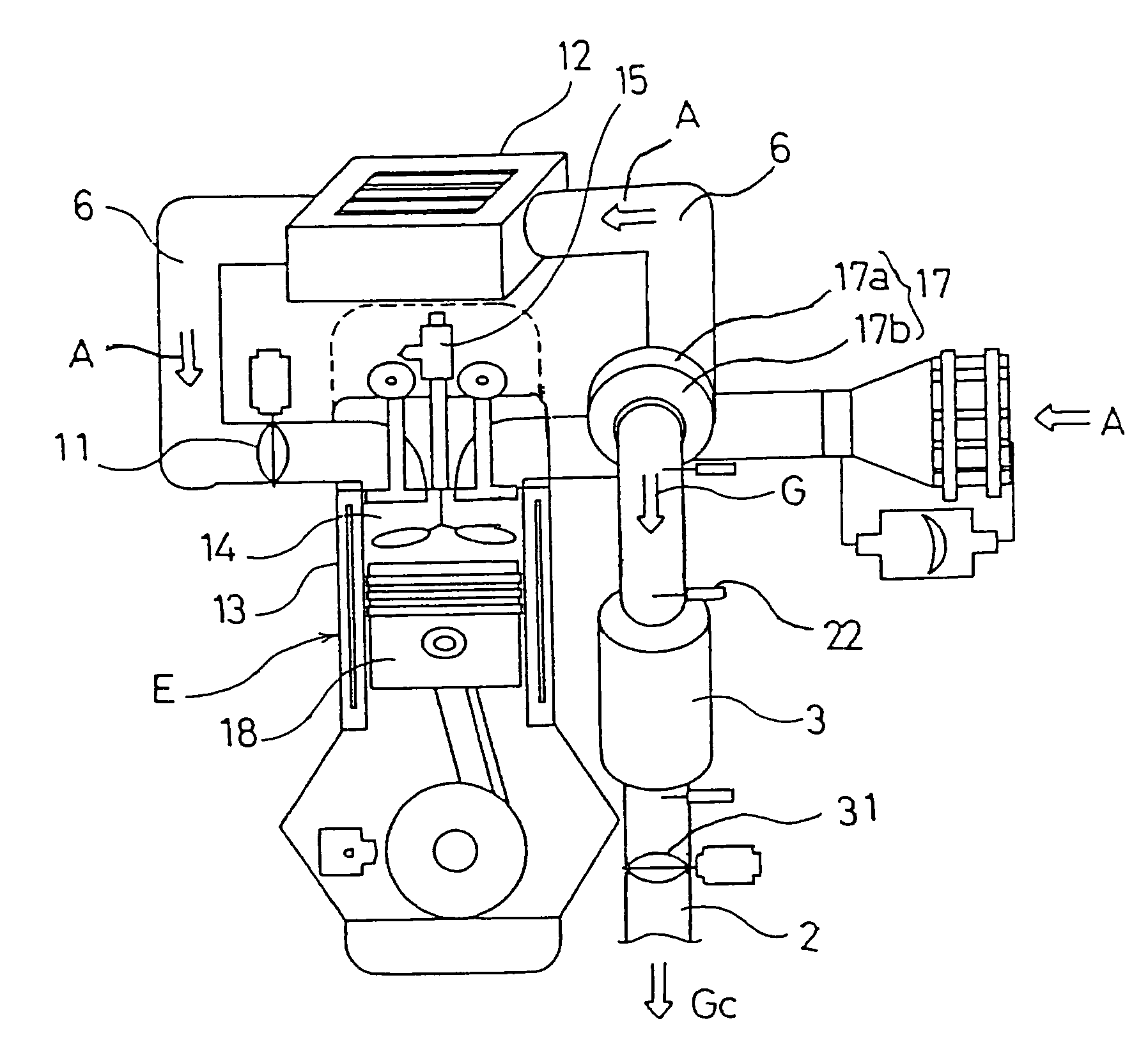
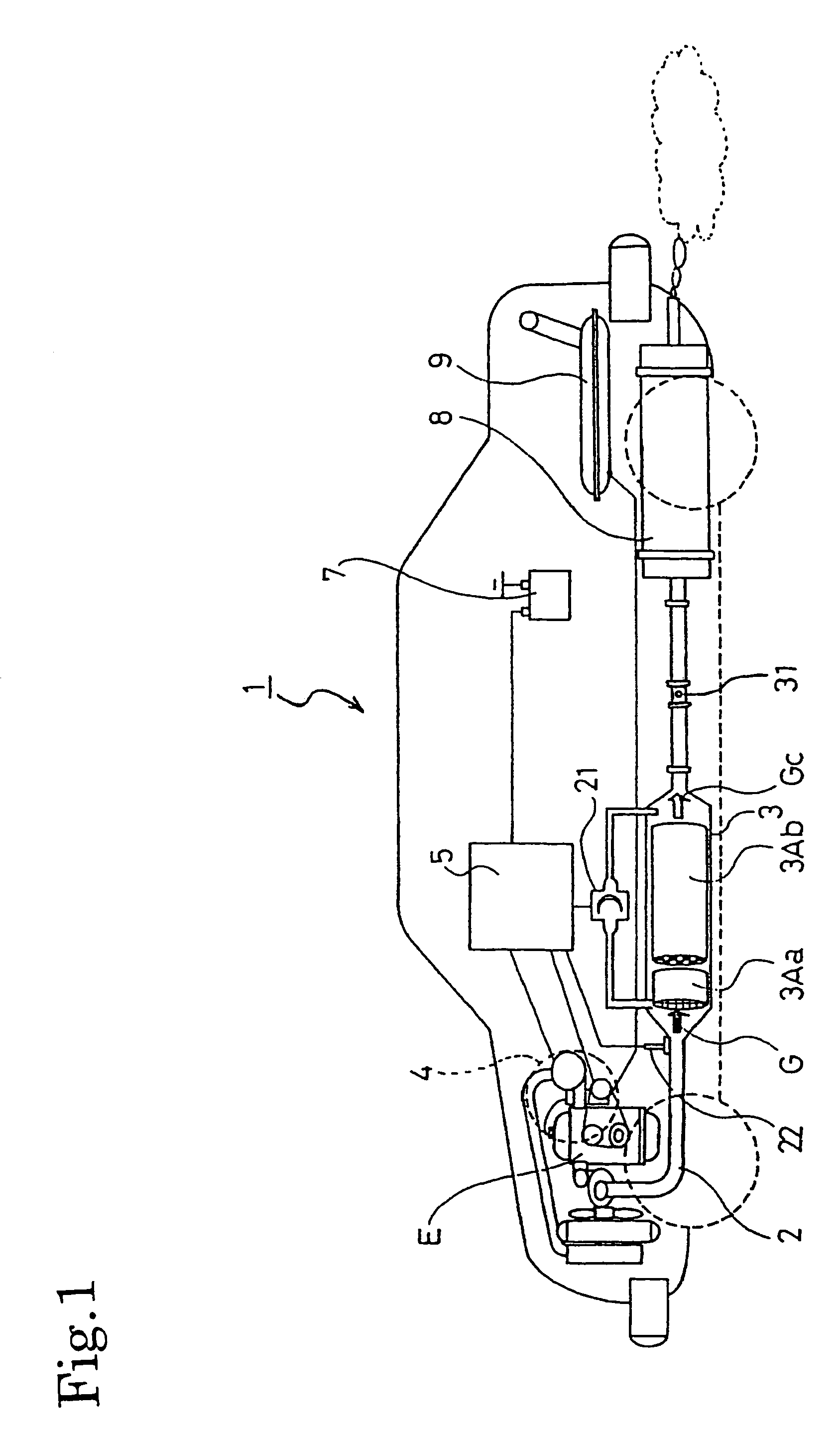
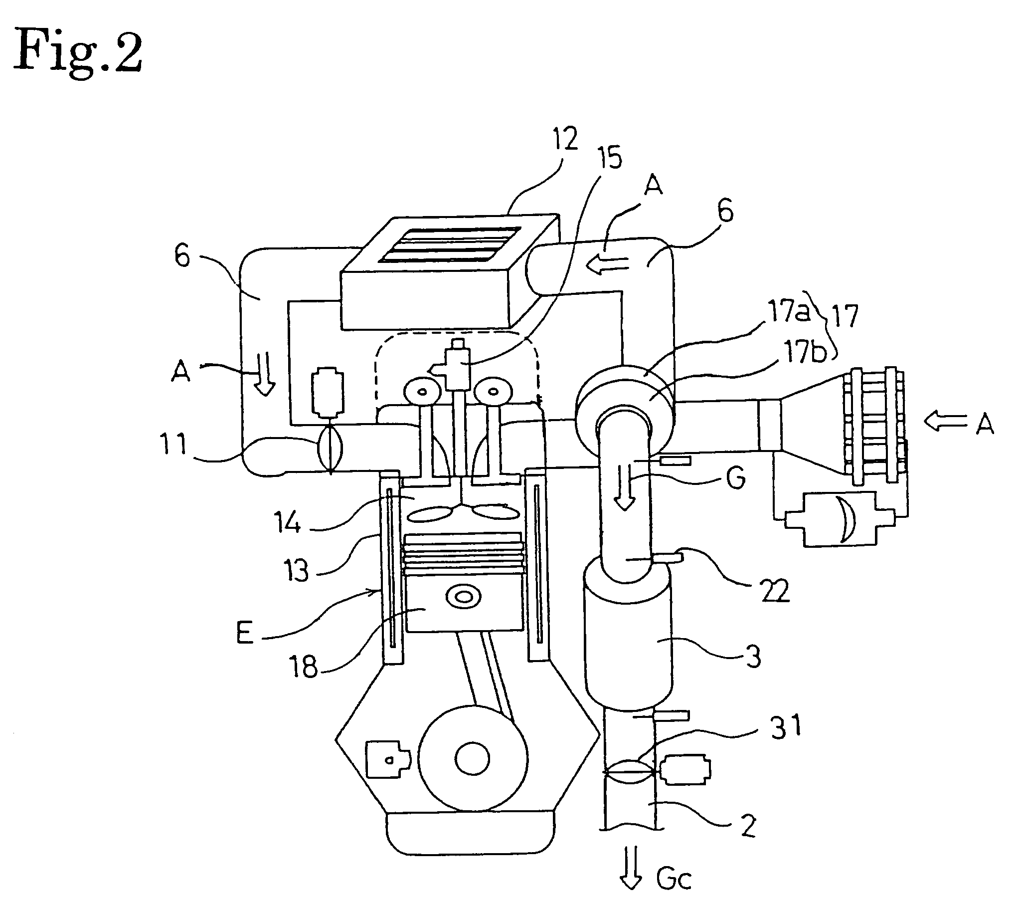
[0052]FIGS. 1 and 2 show a configuration of an exhaust gas purifying system 1 of this embodiment. In this exhaust gas purifying system 1, a continuously regenerating type DPF 3 is set in an exhaust passage (exhaust pipe) 2 connected to an exhaust manifold of a diesel engine E. The continuously regenerating type DPF 3 is constituted of the oxidation catalyst 3Aa at the upstream side and the catalyst-provided filter 3Ab at the downstream side.

[0053]A honeycomb structure of porous ceramic and the like supports an oxidation catalyst such as platinum (Pt), which forms the oxidation catalyst 3Aa. This catalyst-provided filter ...


PUM


Abstract

To provide an exhaust gas purifying system capable of forcibly regenerating DPF by efficiently raising the temperature of exhaust gas even when an exhaust gas temperature is very low at the time of low load and low engine speed such as an idling operation. In an exhaust purifying system (1) having an exhaust throttling valve (31) and a DPF (3) in an exhaust passage and having regeneration control means (P1) for regenerating the DPF (3), the regeneration control means (P1) is provided with an exhaust gas temperature detection means (P22), a fuel injection control means (P11), and an exhaust throttling control means (P12) and includes regeneration control for performing the exhaust gas temperature raising control through the multistage delay injection by the fuel injection control means (P11) and through the exhaust throttling of the exhaust throttling valve (31).

Description

BACKGROUND OF THE INVENTION[0001]The present invention relates to an exhaust gas purifying system for purifying the exhaust gas of an engine by providing a diesel particulate filter.[0002]The restriction of the discharge quantity of particulate matter (hereafter referred to as PM) to be discharged from a diesel engine has been enhanced year by year together with NOx, CO, and HC. Only an improvement of an engine cannot respond to the enhancement of the legal restriction. Therefore, a technique is developed, which reduces the quantity of the PM to be discharged to the open air by collecting the quantity of the PM using a filter referred to as diesel particulate filter (hereafter referred to as DPF).[0003]The DPF for directly collecting the PM includes a monolith honeycomb wall flow type filter made of ceramic and a fiber-type filter obtained by processing ceramic or metal into fiber. The exhaust gas purifying system provided with the above PDF is set in the middle of the exhaust passa...

Claims


Application Information

Patent Timeline
Patent Type & Authority Patents(United States)
IPC IPC(8): F01N9/00F02D41/02F01N3/035F02D9/06F02D41/40F02D9/00F01N7/02F01N7/00F02B29/04F02B37/00F02B29/00F02D9/04F01N3/02F01N3/023F01N13/02
CPCF01N3/0231F01N3/0235F01N3/035F01N9/002F02D9/06F02D41/029F02D41/401F02D41/403F01N13/009F01N13/0097F01N2260/14F01N2430/08F01N2560/06F01N2560/08F02B29/0406F02B37/00F02D41/0245F02D41/402Y02T10/44Y02T10/47Y02T10/40
Inventor ONODERA, TAKAOSHIBATA, HIDETAKAHASEYAMA, TAKASHIIGARASHI, TAKESHIIWASHITA, TAKUROGABE, MASASHITASHIRO, YOSHIHISA
Owner ISUZU MOTORS LTD
Why Eureka
Try Eureka