Drill drive steel

a drive steel and drive plate technology, applied in the direction of drilling pipes, cutting machines, borehole/well accessories, etc., can solve the problems of uncontrolled water loss and floor flooding, relatively expensive and labor-intensive forged drill steel, and the connection of the shank adapter still develops leaks after extended use, etc., to achieve economic and correct manufacturing, without substantial pressure loss

Inactive Publication Date: 2005-11-22
DOVER BMCS ACQUISITION CORP +1
View PDF9 Cites 8 Cited by
  • Summary
  • Abstract
  • Description
  • Claims
  • Application Information

AI Technical Summary

Benefits of technology

[0016]It is an object of the present invention to provide a rotary drilling system that accommodates a low volume air / water flushing fluid and ensures delivery of flushing fluid without substantial pressure loss. Another object is to provide a novel drive steel coupling arrangement for sealable and releasable connection of a drive steel member to a drilling machine chuck. Another principal object is to provide a chuck seating adapter secured to a drive steel member by means preventing axial separation thereof. Another object is to rigidly connect a drive steel starter member to a chuck seating member and provide a leak-proof integral unit. Still other objectives of the invention include elimination of prior connection problems of drive steel softness, loose fit and air / water leakage, disconnection of the drive steel and the like. Another major objective is to provide a safe, strong permanently shanked drill steel that is fully heat treated to 40 Rc, and which is economically and correctly fabricated. These and other objects and advantages will become more apparent hereinafter.

Problems solved by technology

Also in the past, the use of large quantities of drilling fluids for overhead irrigation resulted in uncontrolled water loss and floor flooding.
One prior and continuing problem involves the connection of the drive steel to the chuck of a drilling machine.
The continuing practice in the industry typically utilizes a connector on the tubular drill steel end with a flanged end to seat in the machine chuck; and such connectors are fastened on the drill steel using one of the following techniques:(1) a connector shank is forged onto the round drill steel with the potential problems of (a) being off center, (b) too high or low forging temperature, and (c) improper re-tempering; and, in addition, forged drill steel is relatively expensive and labor intensive;(2) a connector is welded onto thin walled round or hex drill steel which may break due to fatigue and failure resulting from metal softening in the welded area (this practice has been banned in some jurisdictions due to injuries);(3) a connector is press fit into a machined hex drill steel with the potential problems of (a) off center tapering and (b) loosening due to metal flow; or(4) hex drill steel rods are cut to length and a chuck connector is inserted into a drilled rod end with the problems of (a) drill steel softness in the range of 28-35 Rc resulting in bending and also mushrooming on the machine chuck, (b) loosening and pulling apart of the connector, and (c) not being water tight for wet drilling or air tight with loss of vacuum when drilling dry.
However, it has been found that, even with O-ring and silicon sealant applied to such a “pin on” shank, such a shank adapter connection still develops leaks after extended use.
This, of course, compromises that delivery of pressurized flushing fluid to the remote drilling bit end of the drill steel column.

Method used


Image

  • Drill drive steel
  • Drill drive steel
  • Drill drive steel

Examples


Embodiment Construction

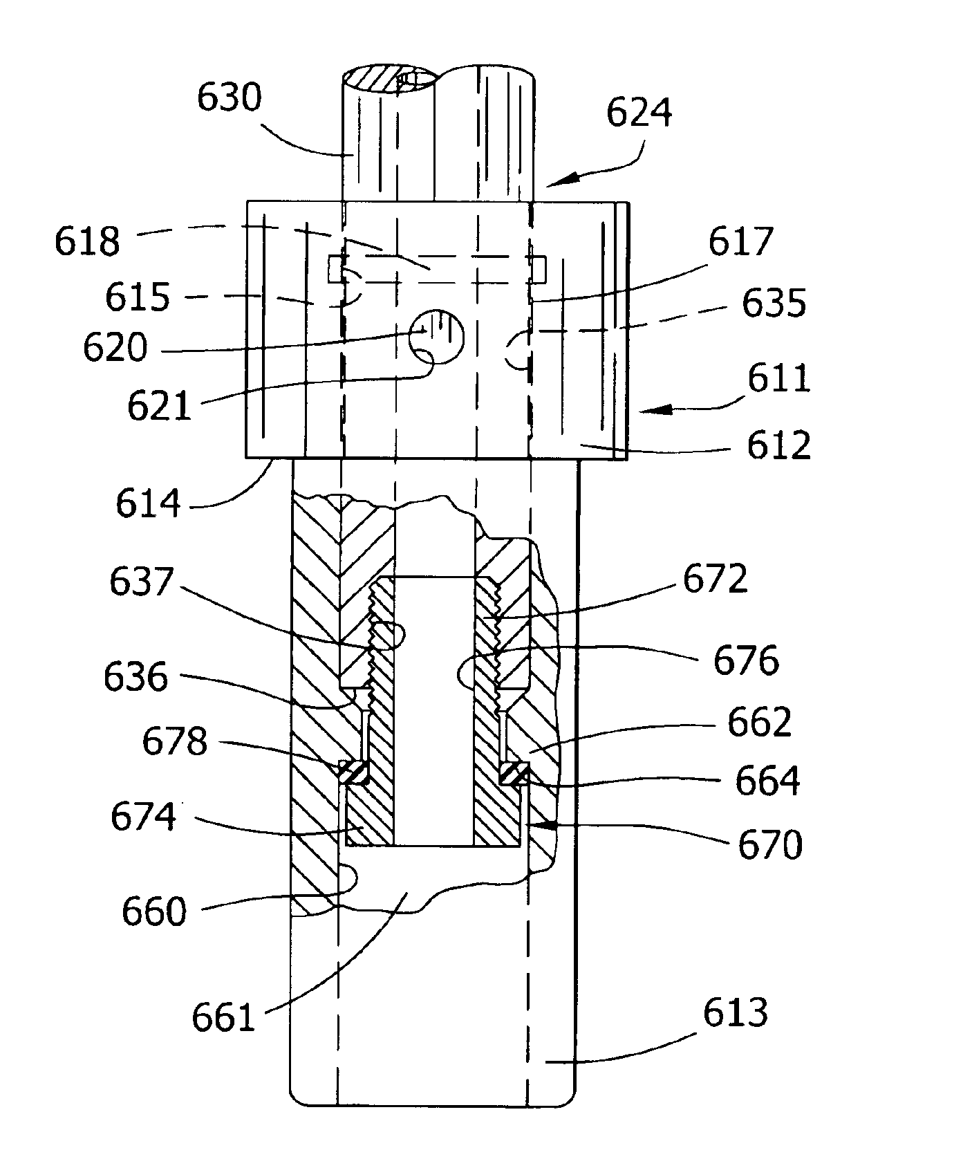
[0031]The present invention pertains generally to mining operations that include roof drilling, longwall mining and continuous mining particularly in which water flushing is non-recoverable; and specifically the invention pertains to improvements in drilling drive steel columns for non-leak systems especially using low volumes of water or air flushing fluids and for maintaining better fluid flow control in a drill steel column.

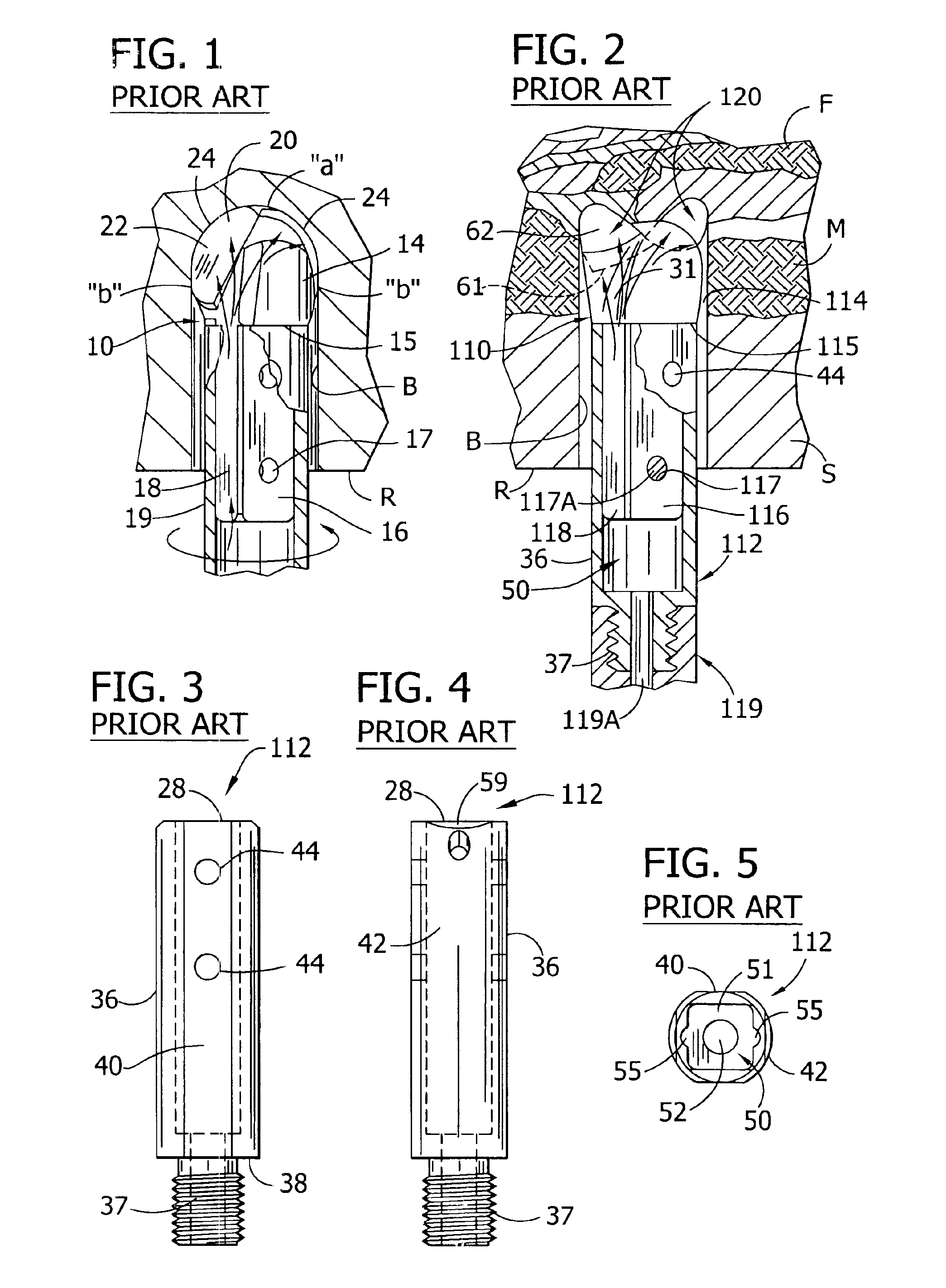
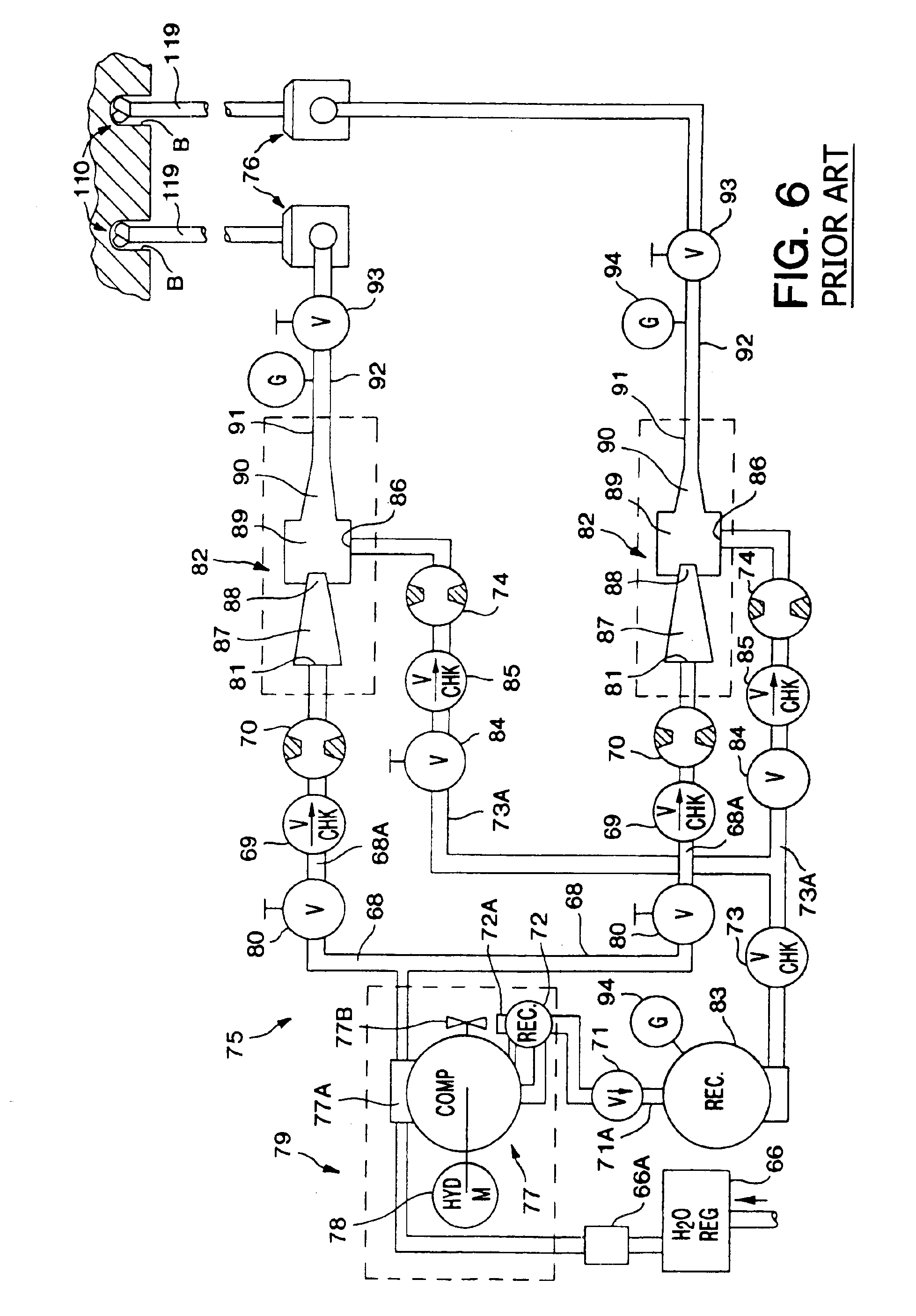
[0032]FIG. 1 shows one embodiment of my earlier non-coring roof drill bit as taught by U.S. Pat. Nos. 5,180,022; 5,303,787 and 5,383,526—the disclosures of which are incorporated by reference. Briefly stated, this non-coring roof drill bit 10 is typically seated on the end of a long rod drive steel 19 (119) of a drilling machine 76, such as a New Fletcher double boom roof bolter (shown in FIG. 6). The bit shank 16 and drive steel 19 have a complementary sliding fit and are typically cross-pinned together at bolt holes 17 or threadedly connected (see FIGS. 7 an...


PUM


Abstract

A drive steel member for driving engagement with a rotary drilling machine, including a chuck adapter having main body and chuck seating means and being constructed and arranged in fixed, sealed relation on one end of the drive steel member.

Description

BACKGROUND OF THE INVENTION[0001]1. Field of the Invention[0002]The invention relates generally to rotary drilling systems, and more specifically to drive steel improvements for drilling systems as used in drilling and boring for roof bolting operations for tunnel construction, mining and the like.[0003]2. Description of the Prior Art[0004]In the fields of industrial, mining and construction tools, polycrystalline diamond (PCD) is now in wide use in making cutting tool inserts, sometimes called polycrystalline diamond compacts (PDC). PCD materials are formed of fine diamond powder sintered by intercrystalline bonding under high temperature / high pressure diamond synthesis technology into predetermined layers or shapes; and such PCD layers are usually permanently bonded to a substrate of “precemented” tungsten carbide to form such PDC insert or compact. The term “high density ceramic” (HDC) is sometimes used to refer to a mining tool having a PCD insert. “Chemical vapor deposition” (C...

Claims


Application Information

Patent Timeline
Patent Type & Authority Patents(United States)
IPC IPC(8): E21B17/02E21B17/03
CPCE21B17/03
Inventor BRADY, WILLIAM J.
Owner DOVER BMCS ACQUISITION CORP
Why Eureka
Try Eureka