Optical unit for optical symbol reader

Inactive Publication Date: 2005-11-29
KEYENCE
View PDF17 Cites 16 Cited by
  • Summary
  • Abstract
  • Description
  • Claims
  • Application Information

AI Technical Summary

Benefits of technology

[0023]In another preferred embodiment, a permanent magnet is provided at one end of the oscillating member, a balancer having a mass almost equivalent to that of the permanent magnet is provided at the other end of the oscillating member, and an electromagnetic coil generating the electromagnetic force with the permanent magnet is provided on the fixing member. Because the balancer is provided, the oscillating member can have its center of gravity located on the central axis of the angular oscillation, so that the angular oscillation of the oscillating member and the scanning of the laser beam are stabilized.
[0024]In still another embodiment, the resiliently urging member is a coil spring stretched between an engagement portion of the oscillating member and an engagement portion of the fixing side member, a permanent magnet is provided at one end of the oscillating member, an electromagne

Problems solved by technology

The self-excitation method has the advantage that there is less exciting current and the drive power efficiency is maximized, but the disadvantage that the resonance frequency is determined by the mechanical structure and the degree of freedom is low.
The separate excitation method has the disadvantage that more drive power is consumed and the drive power efficiency is low, because the resonance phenomenon is not used, although the drive period (frequency) can be set up at will to some extent.
The above angular oscillation structure (1) for the mirror has the problem that the structure of a leaf spring holding portion is complex, and the leaf spring is easily damaged due to an impact upon dropping or vibration during transportation.
However, even if any improvement method is employed, the number of parts is increa

Method used


Image

  • Optical unit for optical symbol reader
  • Optical unit for optical symbol reader
  • Optical unit for optical symbol reader

Examples


first embodiment

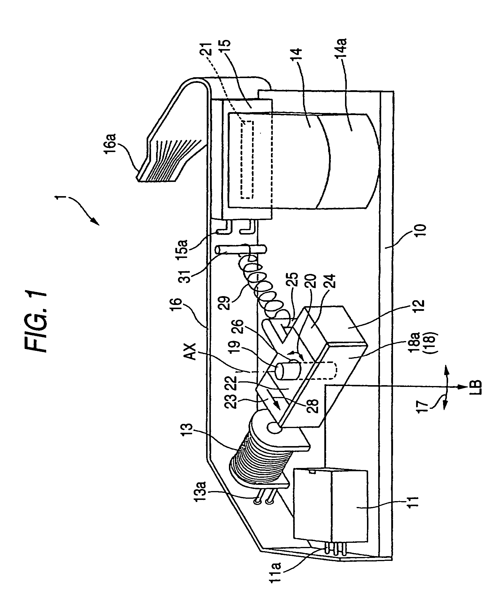
[0040]FIG. 1 is an appearance view of an optical unit for an optical symbol reader according to the present invention. The optical unit for optical symbol reader (hereinafter simply referred to as optical unit) 1 comprises a light source 11, a rotor 12, an electromagnetic coil 13, a converging lens 14, and a photo detector 15, which are disposed on a base 10.

[0041]Wiring means 16 as a flexible substrate is fixed in part around the periphery of the base 10, in which a leader line 11a for the light source 11, a leader line 13a for the electromagnetic coil 13, and a leader line 15a for the photo detector 15 are connected to the wiring means 16. At an end portion 16a of the wiring means 16, an edge connector is formed to connect with an electronic circuit contained in an optical symbol reader (bar code reader). Accordingly, the light source 11, the electromagnetic coil 13 and the photo detector 15 are connected via the wiring means 16 to the electronic circuit. The electronic circuit co...

second embodiment

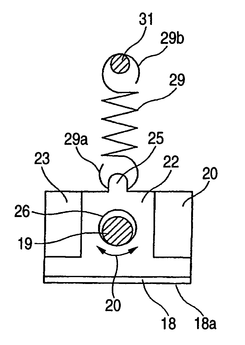
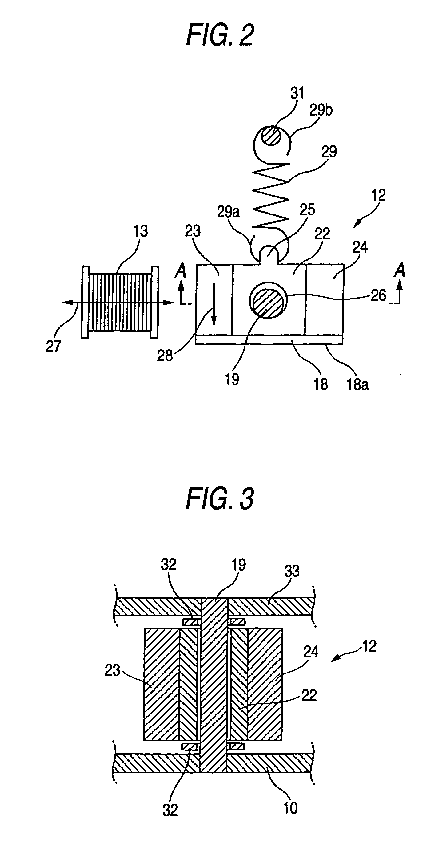
[0067]FIGS. 10A and 10B are views showing an optical unit according to the invention. FIG. 10A is a plan view and FIG. 10B is a side view. In the optical unit 1 of this embodiment, the light source 11, the rotor 12, the electromagnetic coil 13, the converging lens 14 and the photo detector 15 are disposed in a saved space on the base 10. The permanent magnet 23 is fixed at one end of the bearing member 22 having the bearing bore 26 of the rotor 12, and the mirror 18 is fixed at the other end. The electromagnetic coil 13 for generating the magnetic field 27 in parallel and opposite to the direction of magnetization 28 of the permanent magnet 23 is provided facing the magnetic pole of the permanent magnet 23. The reflection face 18a of the mirror 18 forms an angle of about 45 degrees with respect to the urging direction of the coil spring 29.

[0068]Namely, the electromagnetic coil 13 and the light source 11 are disposed in a space across the coil spring 29 for resiliently urging the ro...

third embodiment

[0069]FIGS. 11A and 11B are views showing an optical unit according to the invention, in which FIG. 11A is a plan view and FIG. 11B is a side view. The optical unit 1 of this embodiment has a smaller area of the base 10 by taking a two-stage structure for the optical unit 1 of the embodiment of FIGS. 10A and 10B. That is, the light source 11, the rotor 12, and the electromagnetic coil 13 are arranged in a saved space on the front side of the base 10, and the converging lens 14 and the photo detector 15 are arranged on the back side of the base 10.

[0070]Various embodiments of the present invention have been described above together with the variation examples, but the invention may be embodied by combining these embodiments and variation examples. The invention may be embodied in various forms other than these embodiments and variation examples.

[0071]For example, the optical unit of each embodiment employs a non-coaxial light receiving system in which the optical systems for the opti...


PUM


Abstract

An optical unit for an optical symbol reader comprises an optical scanner for scanning an optical symbol with the laser beam emitted by a light source, by angularly oscillating a reflection face for reflecting the laser beam owing to an electromagnetic force. The optical scanner comprises a loose bearing structure having a shaft and a bearing bore and supporting a rotor having the reflection face to angularly oscillate freely with respect to a base. A certain bearing gap is formed between an outer diameter of the shaft and an inner diameter of the bearing bore. The optical scanner further comprises a coil spring resiliently for urging the rotor in a predetermined direction so that a part of an outer circumferential face of the shaft may be contacted with an inner circumferential face of a bearing bore.

Description

BACKGROUND OF THE INVENTION[0001]1. Field of the Invention[0002]The present invention relates to an optical unit contained in an optical symbol reader such as a bar code reader, and more particularly to an optical scanner for scanning an optical symbol such as a bar code by deflecting a laser beam repeatedly.[0003]2. Description of the Related Art[0004]One type of the optical symbol reader such as the bar code reader scans an optical symbol such as a bar code with a laser beam. In the optical symbol reader of this type, a laser beam emitted from a light source such as a semiconductor laser is deflected in one-dimensional or two-dimensional direction by an optical scanner repeatedly to scan an optical symbol (hereinafter referred to as a bar code). A reflected light from the bar code passes through a converging lens and is detected by a photo detector such as a photodiode to decode the bar code in accordance with an electric signal output from the photo detector.[0005]The optical sca...

Claims


Application Information

Patent Timeline
IPC IPC(8): G02B26/10G06K7/10
CPCG06K7/10653
Inventor OTSUBO, YUSUKE
Owner KEYENCE
Why Eureka
Try Eureka