Powder compacting apparatus and method of producing a rare-earth magnet using the same

Inactive Publication Date: 2005-11-29
HITACHI METALS LTD
View PDF5 Cites 5 Cited by
  • Summary
  • Abstract
  • Description
  • Claims
  • Application Information

AI Technical Summary

Benefits of technology

[0020]It is therefore an object of this invention to provide a practical method of producing a rare-earth magnet that exhibits desirable magnetic properties without causing an accidental ignition even when using a rare-earth alloy powder that is easily oxidized.
[0021]Another object of the present invention is to provide a method of producing a rare-earth magnet in a safe and efficient manner while using a rare-earth alloy powder having a low oxygen concentration.
[0022]An inventive powder compacting apparatus includes: an airtight container capable of storing a rare-earth alloy powder therein; an airtight feeder box moved between a powder-filling position and a retracted position; and an airtight powder supply device capable of supplying the rare-earth alloy powder from the container into the feeder box without exposing the rare-earth alloy powder to an atmospheric air.
[0036]An inventive method is a method of producing a rare-earth magnet by performing a compaction process using the powder compacting apparatus as described above, the method including the steps of: storing a rare-earth alloy powder in the container; operating the powder supply device to supply the rare-earth alloy powder from the container into the feeder box without exposing the rare-earth alloy powder to the atmospheric air; and producing a compact by pressurizing the rare-earth alloy powder supplied from the feeder box into a predetermined space.
[0041]Another inventive method of producing a rare-earth magnet includes the steps of: supplying a rare-earth alloy powder that has been produced through pulverization by a pulverization apparatus in which an oxygen concentration in a pulverization atmosphere is controlled to be 5000 volume ppm or less from the pulverization apparatus into an airtight container without exposing the rare-earth alloy powder to an atmospheric air; supplying the rare-earth alloy powder from the container into an airtight feeder box without exposing the rare-earth alloy powder to the atmospheric air; filling the rare-earth alloy powder from the feeder box into a cavity formed in a die of a compacting apparatus; and making a compact of the rare-earth alloy powder through a pressing process.

Problems solved by technology

However, a magnetic powder of a rapidly-cooled alloy such as a strip-cast alloy is easily oxidized.
Even if oxidization stops short of igniting the powder, the magnetic properties of the powder deteriorate significantly due to the oxidization.
While the heating and ignition of the rare-earth component due to oxidization occur also when compacting a rare-earth alloy powder that has been made by a conventional ingot casting method, the problem is more pronounced when compacting a powder of a rapidly-cooled alloy such as a strip-cast alloy.
In addition to the problem described above, the oxidization of a rare-earth alloy powder also causes a problem as follows.
Although it is preferred to reduce the amount of oxygen in a rare-earth alloy powder that is used to produce an R—Fe—B magnet, as described above, the method of reducing the amount of oxygen in a rare-earth alloy powder to improve the magnet properties has not been realized as a mass-producing technique for the following reason.
Thus, although it was understood that it would be preferred to reduce the amount of oxygen in the rare-earth alloy powder in order to improve the magnetic properties thereof, it was actually difficult to handle a rare-earth alloy powder with such a reduced oxygen concentration at a manufacturing site such as a plant.
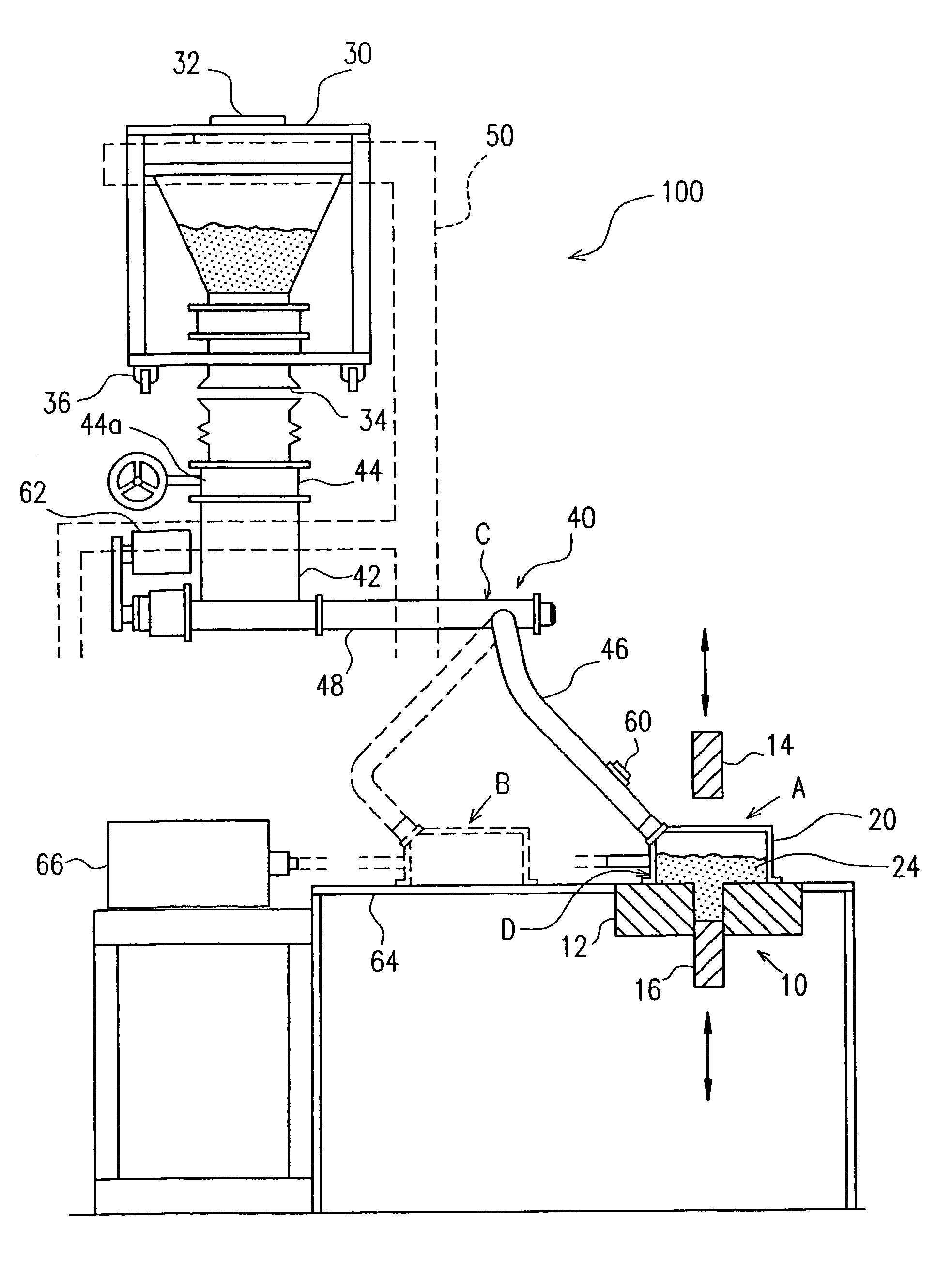
Particularly, in a pressing step for compacting a powder, the temperature of the compact increases due to the frictional heat that is generated between powder particles being compacted and / or the frictional heat that is generated between the powder and the inner wall of the cavity when the compact is taken out of the cavity, thereby increasing the risk of ignition.
However, the conventional compacting apparatus is uneconomical because the gas chamber has a relatively large volume, thereby requiring a large amount of inert gas to fill the gas chamber.
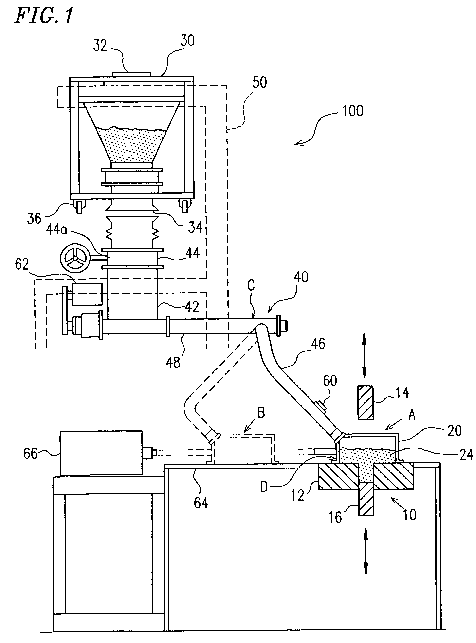
In the conventional compacting apparatus, the inert gas is not supplied directly to the rare-earth alloy powder, and the space around the passageway via which the rare-earth alloy powder (or the compact) is transferred (e.g., the space around the powder feeding device) is also exposed to a high concentration of inert gas, thereby failing to effectively utilize the inert gas.
Moreover, in cases where the inside of the gas chamber is frequently exposed to the air atmosphere (e.g., where die replacement is frequently needed for making various types of compacts), the use of the conventional apparatus significantly reduces the productivity as it requires a long period of time for substituting the gas in the gas chamber with an inert gas each time a die is replaced by another.
Moreover, although the pressing step with a compacting apparatus is automated, the compacting apparatus requires frequent maintenance, and such maintenance often requires a human operator.
If the compacting apparatus is placed in an inert atmosphere, an operator who comes close to the compacting apparatus for trouble shooting may suffer from atmospheric hypoxia.
For these and other reasons, placing the entire compacting apparatus in an inert atmosphere is not a practical approach.
Although such addition of a liquid lubricant forms a thin oily coating on the surface of the powder particles, it cannot sufficiently prevent the oxidization of the powder when a powder whose oxygen concentration is less than or equal to 4000 mass ppm is exposed to the atmospheric air.
However, the presence of the oxidized coating on the powder particle surface increases the total amount of oxygen contained in the powder.
However, this conventional technique leads to a poor productivity because, after filling the cavity of the compacting apparatus with an R—Fe—B alloy powder in the form of a slurry, it is necessary to perform the pressing step while squeezing the oil component out of the alloy powder.

Method used


Image

  • Powder compacting apparatus and method of producing a rare-earth magnet using the same
  • Powder compacting apparatus and method of producing a rare-earth magnet using the same
  • Powder compacting apparatus and method of producing a rare-earth magnet using the same

Examples


Embodiment Construction

[0049]According to the present invention, a rare-earth alloy powder is supplied into a feeder box via a substantially sealed supply passageway in order to avoid exposing the powder to atmospheric air. As a result, it is possible to produce a rare-earth magnet that exhibits desirable magnetic properties without causing an accidental ignition even when employing a rare-earth alloy powder that is very easily oxidized (i.e., a low-oxygen powder).

[0050]An embodiment of the present invention will now be described with reference to the accompanying drawings.

[0051]FIG. 1 illustrates a main part of a powder compacting apparatus 100 of an embodiment of the present invention. The powder compacting apparatus 100 includes a die set 10 for performing a compaction process, a feeder box (powder-filling device) 20 that is moved between a powder-filling position A and a retracted position B, and a container (material hopper) 30 capable of storing a rare-earth alloy powder therein.

[0052]The die set 10...


PUM

PropertyMeasurementUnit
Temperatureaaaaaaaaaa
Concentrationaaaaaaaaaa
Flexibilityaaaaaaaaaa

Abstract

The present invention aims to prevent heating and ignition of a material powder of a rare-earth alloy while reducing the oxygen content thereof so as to improve the magnetic properties of the rare-earth magnet. A rare-earth alloy powder is compacted by using a powder compacting apparatus including: an airtight container capable of storing a rare-earth alloy powder therein; an airtight feeder box moved between a powder-filling position and a retracted position; and an airtight powder supply device capable of supplying the rare-earth alloy powder from the container into the feeder box without exposing the rare-earth alloy powder to the atmospheric air.

Description

FIELD OF THE INVENTION[0001]The present invention relates to a method of producing an R—Fe—B type rare-earth magnet. More specifically, the present invention relates to a powder compacting apparatus that is particularly suitable for use with a rare-earth alloy powder having a reduced oxygen content, and a method of producing a rare-earth magnet using the same.BACKGROUND OF THE INVENTION[0002]A rare-earth alloy sintered magnet is made by compacting a magnetic powder that has been obtained by pulverizing a rare-earth alloy, and then subjecting the product to a sintering step and an aging step. Currently, two types of rare-earth alloy sintered magnets are widely used in various fields: samarium-cobalt magnets and neodymium-iron-boron magnets. Particularly, neodymium-iron-boron magnets (hereinafter referred to as “R—Fe—B magnets”, wherein R denotes a rare-earth element and / or Yttrium, Fe denotes iron, and B denotes boron.) have been actively employed in various electronic devices becaus...

Claims


Application Information

Patent Timeline
IPC IPC(8): B22F3/00B30B15/30H01F41/02
CPCB22F3/004B30B15/304H01F41/0266B22F2999/00B22F2201/10B22F2202/01Y10S425/815
Inventor KUNIYOSHI, FUTOSHITOKUHARA, KOKIKANNO, KUNITOSHIMORIMOTO, HITOSHIOHTANI, TOMOIKUONO, RYOJI
Owner HITACHI METALS LTD
Why Eureka
Try Eureka