Center-tap transformers in integrated circuits

a transformer and integrated circuit technology, applied in the direction of fixed transformers or mutual inductances, basic electric elements, inductances, etc., can solve the problems of introducing undesirable artifacts or distortions to signals, destabilizing circuits, and paralysis, so as to reduce costs, remove undesirable cross-coupling, and improve performan

Inactive Publication Date: 2005-11-29
ZHANG MINGHAO MARY +1
View PDF11 Cites 11 Cited by
  • Summary
  • Abstract
  • Description
  • Claims
  • Application Information

AI Technical Summary

Benefits of technology

[0014]Depending on the winding configurations, current flows in respective inductors can be in same or opposite directions, resulting in symmetric or asymmetric winding configurations. The symmetric or asymmetric winding configurations can be advantageously used in various circuits or systems resulting in better performance and lower costs.
[0015]There are many benefits, advantages and features in the present invention. One of them is to integrate several transformers without occupying several spaces that would otherwise be occupied by the transformers. Another one of them is a mechanism to isolate the integrated transformers by depositing grounding stripes between every pair of inductors or grounding shields across layers so that undesirable cross-coupling can be removed or minimized.

Problems solved by technology

Further, it is well understood that the multiple individual silicon spaces for the transformers can result in the parasitic effects.
These unwanted transformers may introduce undesirable artifacts or distortions to signals and even destabilize circuits.

Method used


Image

  • Center-tap transformers in integrated circuits
  • Center-tap transformers in integrated circuits
  • Center-tap transformers in integrated circuits

Examples


Embodiment Construction

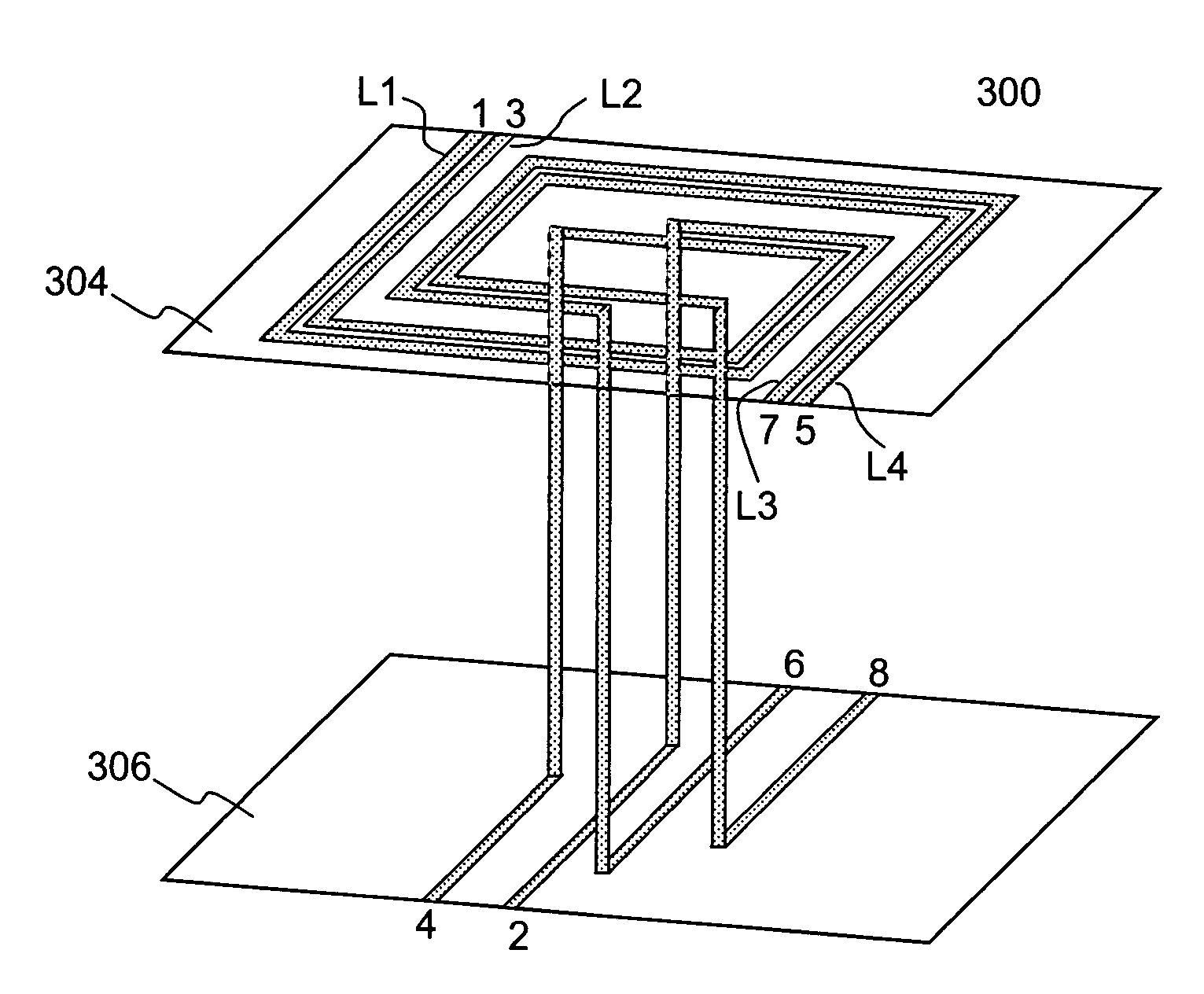
[0044]The present invention pertains to integrating multiple transformers in silicon without occupying multiple individual silicon spaces that would otherwise be occupied by the multiple transformers. It is well understood that the multiple individual silicon spaces for the transformers can introduce undesirable parasitic effects (e.g. from extended connections around a circuit). The implementation of multiple transformers in a confined single silicon space will advantageously reduce the parasitic effects. As a result, an integrated circuit chip employing these transformers implemented in accordance with the present invention will be of small size and thus the cost of the integrated circuit chip can be substantially reduced. To remove or minimize undesired cross-couplings between inductors in a layer or inductors on layers that are not supposed to be coupled, a grounding stripe is formed, deposited, provided or deposited between the inductors or a grounding shield (wall) is provided...


PUM

PropertyMeasurementUnit
voltageaaaaaaaaaa
inductanceaaaaaaaaaa
conductingaaaaaaaaaa

Abstract

Techniques for implementing transformers with center-taps are described. Based on an overlay winding structure, according to one embodiment, the primary and the secondary of the transformer are respectively formed on two separate layers that are stacked on top of each other, wherein the secondary includes two segments, the two respective terminals of the two segments are coupled together to a component in a circuit to form a center-tap of the secondary. According to another embodiment, three or more separating windings are formed on separate layers. At least one of the windings is a conducting stripe wound in loops and includes a center-tap that extends across but not electrically connected to the loops of the conducting stripe by detouring the conducting stripe through other layers.

Description

CROSS REFERENCE TO RELATED APPLICATIONS[0001]This application is a continuation-in-part application of U.S. application Ser. No.: 10 / 325,038, filed Dec. 20, 2002, now U.S. Pat. No. 6,683,480 which is a continuation-in-part of U.S. patent application Ser. No.: 10 / 137,988, filed May 2, 2002, now U.S. Pat. No.: 6,559,693, which claims the priority of U.S. patent application Ser. No. 09 / 947,643, filed Sep. 5, 2001, now U.S. Pat. No. 6,433,595, all of which are incorporated herein for all purposes.BACKGROUND OF THE INVENTION[0002]1. Field of the Invention[0003]The invention is generally related to the area of integrated circuits designs. More particularly, the invention is related to designs of multiple inductors or transformers in integrated circuits, wherein the transformers have strong magnetic couplings but do not occupy multiple areas. The invention is also related to transformers with one or more center-taps.[0004]2. The Background of Related Art[0005]An inductor is a passive elect...

Claims


Application Information

Patent Timeline
Patent Type & Authority Patents(United States)
IPC IPC(8): H01F5/00H01F17/00H01F19/04H01L23/522H01L27/08H01L29/00H03F3/195H03F3/45H03F3/60
CPCH01F17/0006H01L23/5227H03F3/195H03F3/45183H03F3/4521H03F3/604H01F17/0013H01F19/04H01F2017/008H01L27/08H03F2203/45638H03F2203/45702H03F2203/45731H01L2924/0002H01L2924/00
Inventor ZHANG, MINGHAO MARYTUNG, JOHN C.
Owner ZHANG MINGHAO MARY
Why Eureka
Try Eureka