Optical resonant gel display

a gel display and optical resonant technology, applied in the field of electronic and wireless low cost paperlike displays, can solve the problems of high cost, lack of significant market adoption of prior art paperlike displays, and difficulty in automating manual labeling, and achieve the effects of reducing cost, cost-effectiveness, and facilitating us

Inactive Publication Date: 2005-11-29
LIGHT MODULATION
View PDF4 Cites 44 Cited by
  • Summary
  • Abstract
  • Description
  • Claims
  • Application Information

AI Technical Summary

Benefits of technology

[0034]It is another object to provide the lowest cost optical detector for use in applications such as electronic shelf tag systems and merchandising signage systems that use light modulation as the network in a manner that is cost-effective and is the simplest and most convenient for the users.
[0035]Another innovation proposed by the present invention is the arrangement of these four layers or components in a manner so as to make their manufacturing process most efficient and permit high-speed production and also, so as to minimize the total surface and so as to provide a new type of construct that combines the existing layers into an innovative multi-layered detector capable of useful use together with any optical data communications system.

Problems solved by technology

Problems like the automation of manual labeling have presented a particularly difficult challenge to resolve.
The lack of any significant market adoption of prior art paper-like display is directly related to higher cost, greater complexity in the electrochemical and physical properties of the electrophoretic and other paper-like systems and the implied higher costs related with RF and IR installations.
These problems have rendered electronic signage as the last area to be automated with a satisfactory technology in the supermarket and retail industries.
For years shelf tags have failed to be automated due to the problems presented by high cost, complexity and lack of image quality.
Due to the chosen system architecture by the prior art, both of these types of wireless systems RF and IR represent higher power and infrastructure costs.
Some of the limitations of the prior art include: (1) high-cost of wireless communications hardware; (2) lower image quality; (3) unsuitability for large-surface products like road signs or billboards; (3) high power-consumption and (4) lack of a truly paper-white quality surface with similar characteristics to paper including high contrast and high quality colors that include the use of near perfect white as a paper-like background.
Nevertheless, whenever these paper-like signs are employed in a wireless application that requires a low-cost per unit, this prior art has proven to be high in power consumption, i.e. requiring batteries and also high in cost due to the related hardware involved in the radio frequency or infrared wireless networking of these signs.
In the field of electronic price tags, prior art designs typically use a plastic housing and a small LCD screen which fails to provide users with color or sufficient image quality for branding.
Prior art display technology has largely failed to deliver the value to users due to high cost per unit, complex-retrofitting installations, and complicated integration with different software systems.
In this field of use, hardware specific flaws like high power, rigid architecture, have directly contributed to a very low adoption rate.
Despite the fact that prior art innovations in electrophoretic encapsulation have led to better image quality, the problems related with wireless communications like RF and IR hardware and the ensuing large power consumption ratios have continued to be present.
For many years different electrophoretic display technologies have sought and failed to gain market acceptance and widespread usage.
However, since many of the capsules fail to align perfectly in orientation every time, the resolution and color of the surface is of lesser quality.
Application of a second electric field may then cause many of the second particles to translate, thereby disorienting the anisotropic particles and resulting in a distortion of the optical qualities of the display's surface.
Likewise, the orientation of the anisotropic particles may allow easier translation of the plurality of second particles, also resulting in a deterioration of the optical characteristics.
This method presents greater complications in terms of precise fulfillment of the chemical properties of the suspension fluid and the particles and leads to higher cost of manufacturing.
The challenges posed by integrating diverse types of particles with complicated chemical and physical properties renders many of the proposed innovations in the prior art expensive and difficult to manufacture to such exacting parameters.
The micro-coating techniques and elaborate combinations of electrophoretic particles required are expensive and result in slower manufacturing processes methods.

Method used


Image

  • Optical resonant gel display
  • Optical resonant gel display
  • Optical resonant gel display

Examples


Embodiment Construction

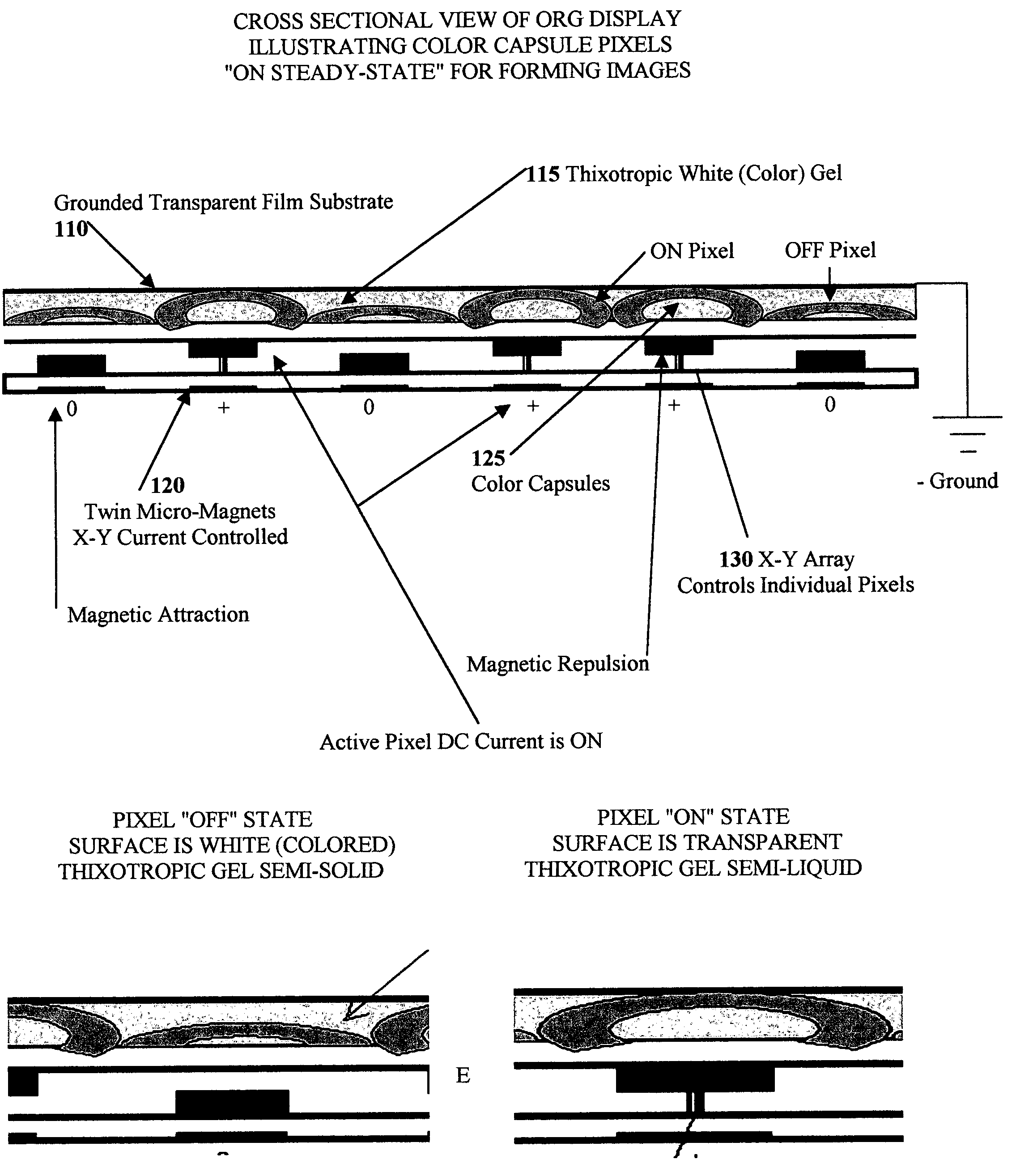
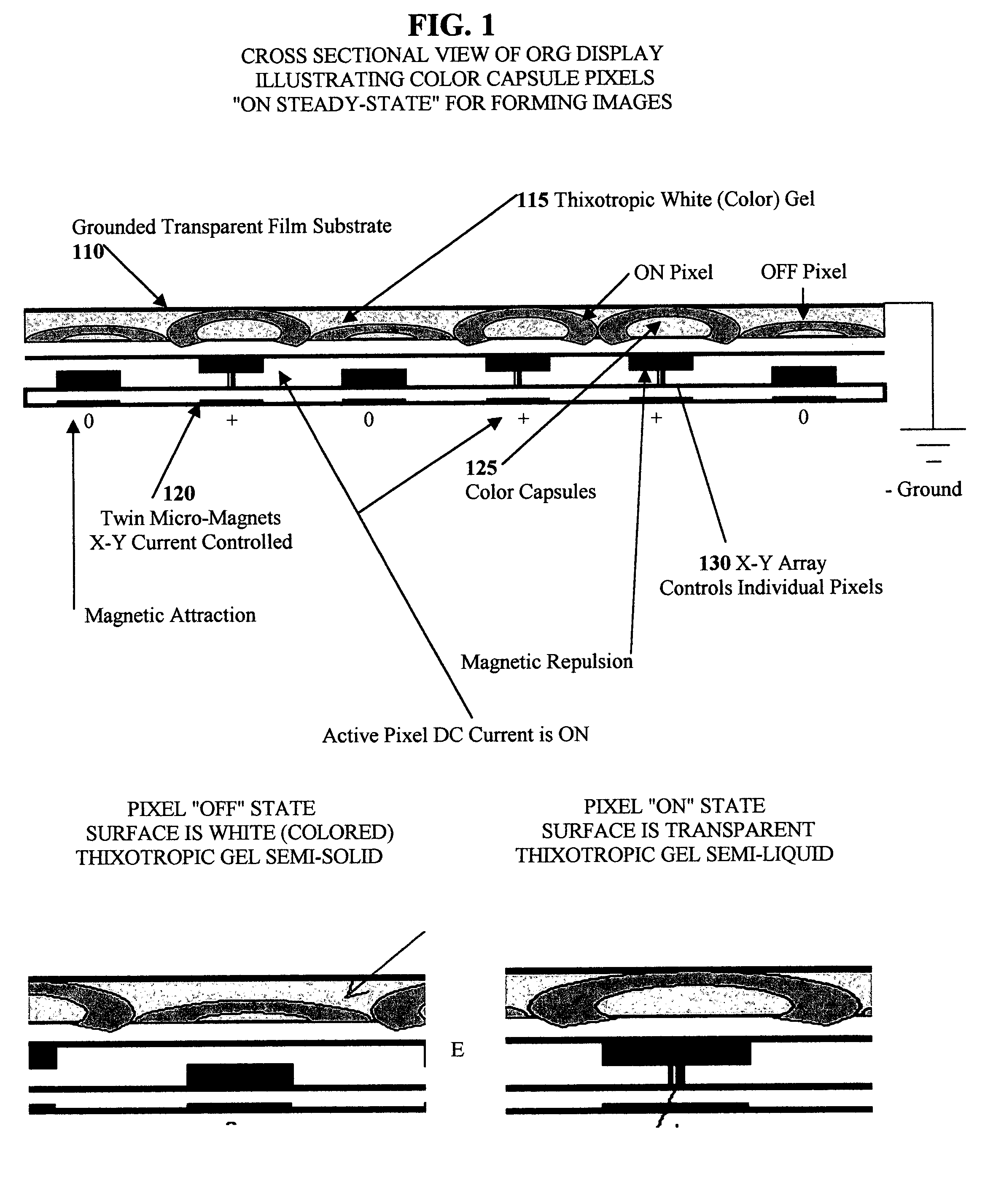
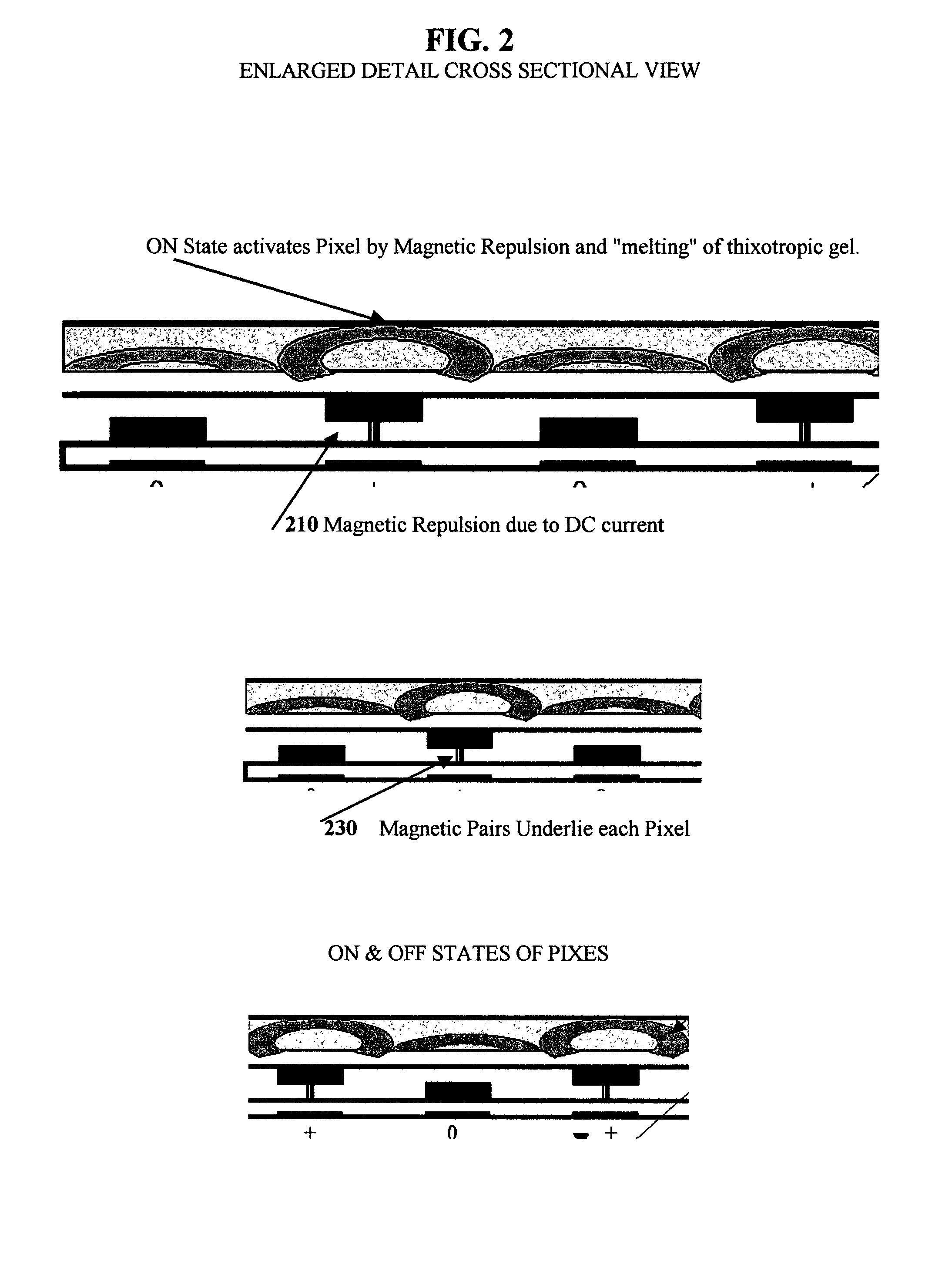
[0047]The preferred embodiment is a flexible composite layered architecture comprising:

[0048](i) a white (or any other suitable color) thixotropic gel coating first surface layer, used in conjunction with an electro-mechanical addressable X-Y pixel array located directly underneath this first layer. Images are formed on the surface of this display by changing the state of transparency of the gel surface, from semi-solid to semi-liquid as a result of thixotropic bond shearing. In addition to the electrical current covalent bond shearing of the gel, images are also formed by each active pixel being forced upwards by magnetic repulsion between the twin-micro-magnet elements to help form images and break the surface tension of the gel and press against the front layer film and forming a visible pixel or; downwards to help erase the image by means of magnetic attraction between the two micro-magnets located directly underneath each pixel.

[0049](ii) a second layer located directly behind ...


PUM


Abstract

A white or colored thixotropic gel is used in conjunction with an electro-mechanical addressable X-Y pixel array composed of micro-magnet pairs in order to produce a re-writable display surface for forming images. Images are formed on the surface of this display by changing the state of transparency of the gel surface, from semi-solid to semi-liquid as a result of thixotropic bond shearing. In addition, pixels are capsules filled with any given color. Furthermore, each active color capsule is forced upwards by magnetic repulsion between the twin-micro-magnet elements to help form images and break the surface tension of the gel and press against the front layer film and forming a visible pixel or; downwards to help erase the image by means of magnetic attraction between the two micro-magnets located directly underneath each pixel. In an embodiment of this invention, four or more layers of materials are bonded together in a flexible construct in order to provide to users a low-cost electronic paper-like display.

Description

[0001]This application claims the benefit of Provisional Application Ser. No. 60 / 403,520 filed Aug. 14, 2002.FIELD OF THE INVENTION[0002]The present invention relates generally to electronic and wireless low cost paper-like displays and more particularly relates to electrophoretic and other types of bi-stable displays for applications like the automation of shelf tags, where the realization of the lowest cost architecture for a wireless display system is critical for large-scale adoption.[0003]The present invention relates generally to optical data communications systems and more particularly relates to data communications systems which employ modulated ambient light as the carrier of information. The present innovation is an optical data detector which utilizes different layers of materials so as to produce a wireless paper-like electronic display, capable of forming and refreshing images broadcasted by an optical information network to the detector so as to enable alphanumeric and...

Claims


Application Information

Patent Timeline
Patent Type & Authority Patents(United States)
IPC IPC(8): G02B26/02G09G3/34
CPCG02B26/004G02B26/02G09G3/3486G09G2380/04
Inventor CABRERA, FLORENCIO
Owner LIGHT MODULATION
Why Eureka
Try Eureka