Solid electrolytic capacitor and manufacturing method

a technology of solid electrolytic capacitors and manufacturing methods, which is applied in the manufacture of capacitors, fixed capacitor details, fixed capacitors, etc., can solve the problems of small volume efficiency of capacitor elements to reduce capacitance and increase impedance, and the frame inserted into the case should be much limited in size reduction, so as to achieve the effect of improving the contact structure, reducing the volume efficiency, and reducing the size of the fram

Active Publication Date: 2005-11-29
SAMSUNG ELECTRO MECHANICS CO LTD
View PDF7 Cites 43 Cited by
  • Summary
  • Abstract
  • Description
  • Claims
  • Application Information

AI Technical Summary

Benefits of technology

[0015]An object of the present invention is to provide a solid electrolytic capacitor for improving a contact structure of a capacitor element and a lead frame such that the capacitor element has greater volume efficiency to achieve an enough electrostatic capacitance though being miniaturized.
[0016]Another object of the present invention is to provide a solid electrolytic capacitor and a manufacturing method thereof in which great volume efficiency can be secured while reliability can be guaranteed when a chip is mounted, and mass production can be more easily performed.

Problems solved by technology

As a result, the conventional tantalum capacitor has a drawback in that the capacitor element has a small volume efficiency to reduce capacitance and increase impedance.
Further, since the lead frame is required to be much limited in reduction of a size itself so as to firmly fix the lead frame inserted into the case, the lead frame inserted into the case should be much limited in size reduction.
That is, it is required to firmly fix the lead frame by molding; if the lead frame is excessively reduced in size, there is a drawback in that the lead frame is not firmly fixed.
However, the above structured chip capacitor can achieve an advantageous increase of the volume efficiency, whereas has a drawback generated when the chip is mounted.
Accordingly, at the time of soldering, the conventional chip capacitor has a drawback in that the contact area between the solder and the terminal is not formed normally.
This causes unreliability in the electrical connection of the chip and the substrate.

Method used


Image

  • Solid electrolytic capacitor and manufacturing method
  • Solid electrolytic capacitor and manufacturing method
  • Solid electrolytic capacitor and manufacturing method

Examples


Embodiment Construction

[0037]Reference will now be made in detail to the preferred embodiments of the present invention, examples of which are illustrated in the accompanying drawings. Wherever possible, the same reference numbers will be used throughout the drawings to refer to the same or like parts.

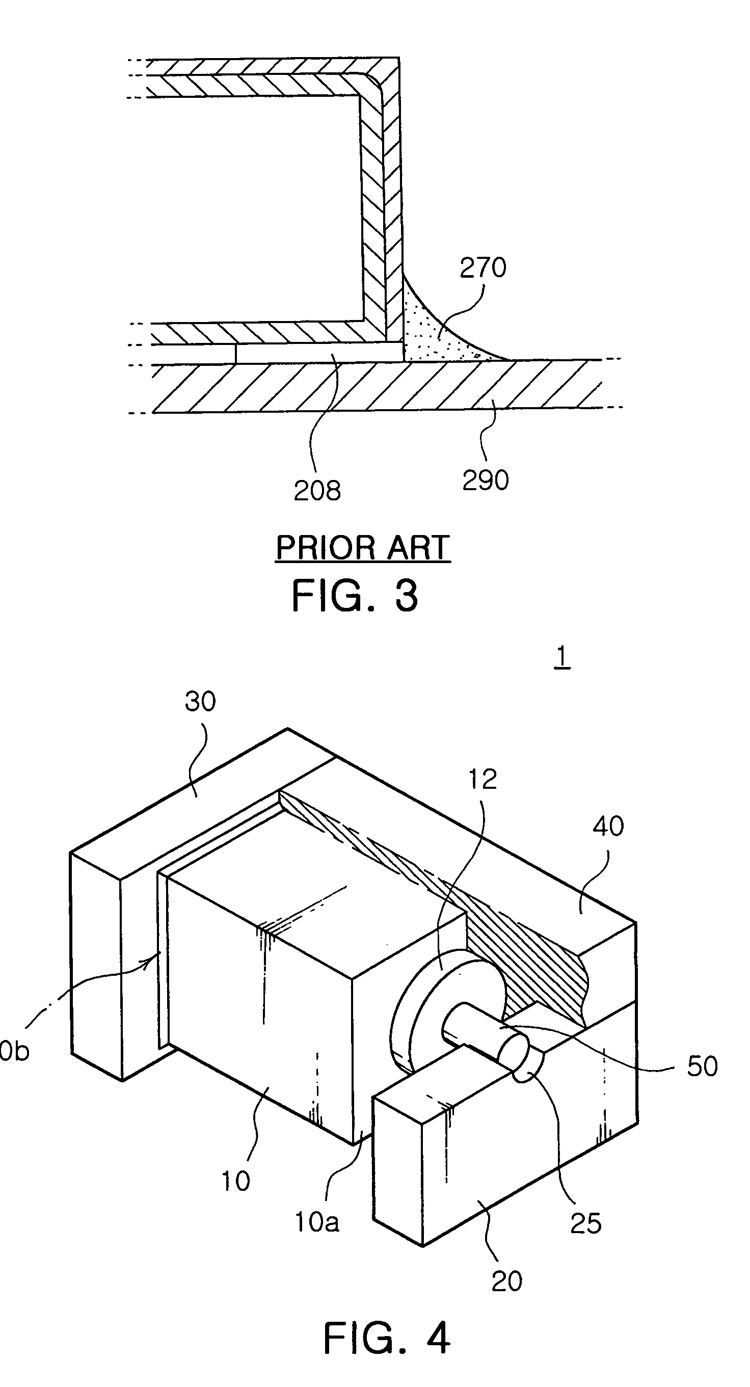
[0038]FIG. 4 is a perspective section view illustrating an internal structure of a solid electrolytic capacitor according to a preferred embodiment of the present invention, and FIG. 5 is a section view illustrating the capacitor of FIG. 4.

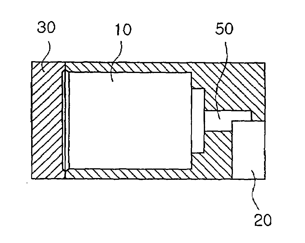
[0039]The inventive solid electrolytic capacitor includes a capacitor element 10. The capacitor element 10 is a dielectric element manufactured by compressing and shaping a tantalum oxide (Ta2O5) powder in a cuboid-shape. The dielectric element is not limited to tantalum (Ta), but can be also selectively formed of other materials such as a niobium (Nb) oxide.

[0040]The capacitor element 10 is formed in a rectangular column-shape. The capacitor element 10 includes a front su...


PUM

PropertyMeasurementUnit
sizeaaaaaaaaaa
conductiveaaaaaaaaaa
volume efficiencyaaaaaaaaaa

Abstract

Disclosed is a solid electrolytic capacitor, wherein a capacitor element has a front surface from which an anode lead wire is protruded. A cathode layer is formed on an outer surface of the capacitor element. A flat-shaped cathode lead frame is surface-contacted with an entire rear surface of the capacitor element. A flat-shaped anode lead frame has a concave portion formed at a central end portion thereof, in which the anode lead wire of the capacitor element is seated and electrically connected to the concave portion. A mold is formed to surround the capacitor element, to partially surround the anode lead frame, and to contact a face of the cathode lead frame which is surface-contacted with the capacitor element.

Description

CROSS-REFERENCE TO RELATED APPLICATION[0001]This application claims to benefit of Korea Patent application No. 2003-80508, filed Nov. 14, 2003.BACKGROUND OF THE INVENTION[0002]1. Field of the Invention[0003]The present invention relates to a solid electrolytic capacitor and a manufacturing method thereof in which a volume efficiency is improved, and more particularly, to a solid electrolytic capacitor for improving a contact structure of a capacitor element and a lead frame such that the capacitor element has a greater volume to improve the volume efficiency.[0004]2. Description of the Related Art[0005]Generally, a solid electrolytic capacitor called a tantalum capacitor is widely used in an application circuit having a low rating voltage range as well as in a general industrial device, and in particular is widely used in a circuit in which a frequency characteristic is of question. Generally, the solid electrolytic capacitor is widely used to reduce a noise of a portable communicat...

Claims


Application Information

Patent Timeline
Patent Type & Authority Patents(United States)
IPC IPC(8): H01G9/08H01G2/06H01G4/228H01G9/00H01G9/012H01G9/042H01G9/10H01G9/145H01G9/15H01G13/00
CPCH01G2/065H01G9/012H01G9/15H01G9/042Y10T29/417
Inventor OH, HYUN SUBKIM, JAE KWANGPARK, JAE JUN
Owner SAMSUNG ELECTRO MECHANICS CO LTD
Why Eureka
Try Eureka