
Rotational atomizer with external heating system

a technology of rotating atomizer and heating system, which is applied in the direction of superimposed coating process, liquid/solution decomposition chemical coating, lighting and heating apparatus, etc., can solve problems such as painting errors and problems, and achieve the effect of high drive outpu

Active Publication Date: 2005-12-06
DURR SYST INC
View PDF59 Cites 28 Cited by
  • Summary
  • Abstract
  • Description
  • Claims
  • Application Information

AI Technical Summary

Benefits of technology

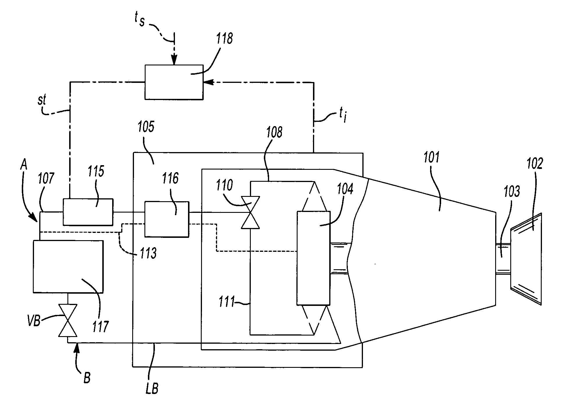
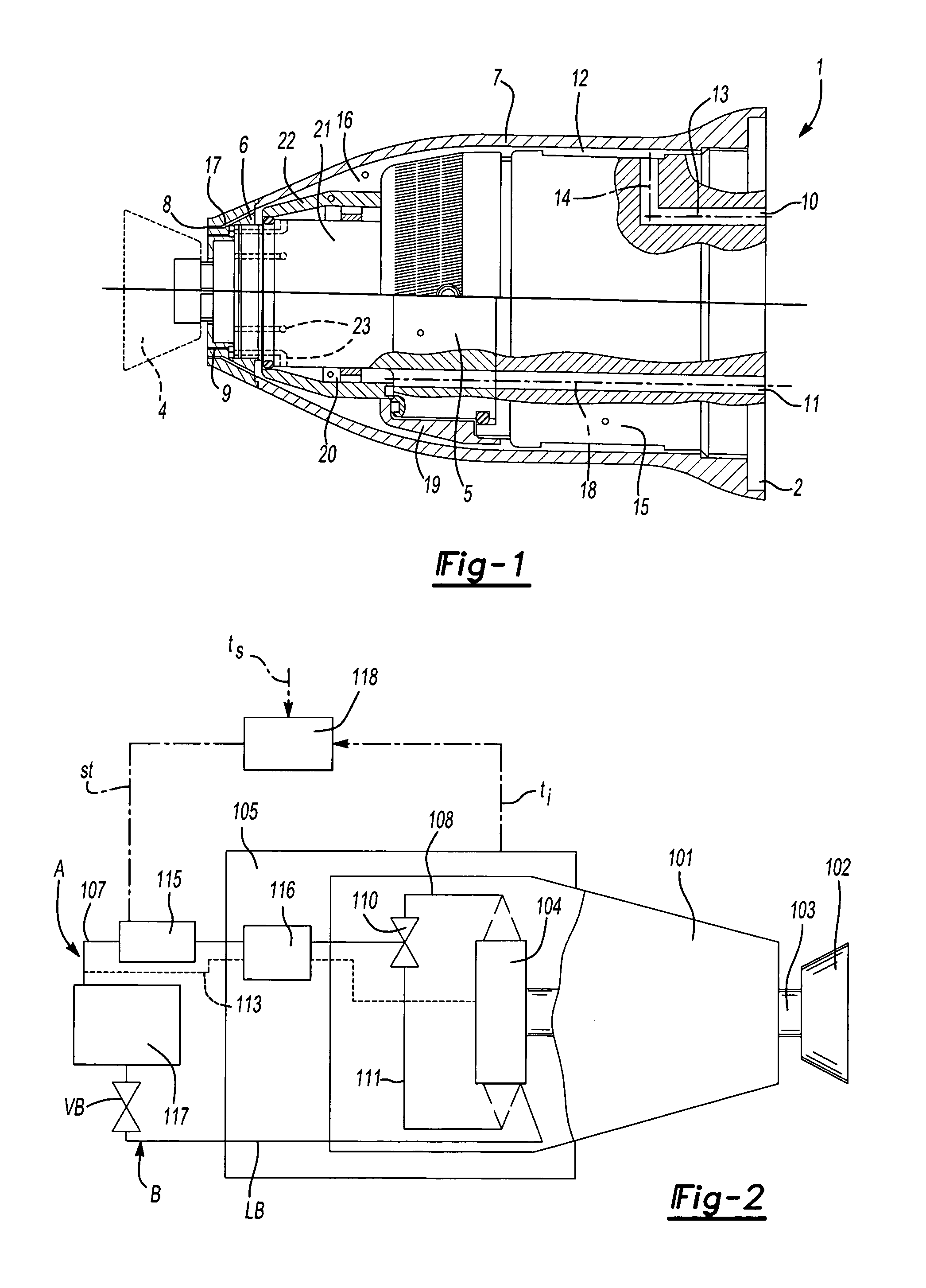
[0009]The heating of the exhaust gas of the turbine can be especially advantageous by means of a heat exchanger, which carries on one side an air flow from the exhaust air and on the other side an air flow from the supply air of the turbine or also from a separately supplied liquid or gaseous medium, such as heated air. When the heated supply air is guided through the heat exchanger, a single heating device is sufficient for heating the supply air and also the exhaust gas as an additional measure, without producing additional consumption of air for this heating at two different locations. Here, it is also advantageous that supply air channels and adjacent components can be prevented from becoming too strongly heated.
[0019]All of the possibilities described above for preventing too strong a cooling can be used alone or also in any combination and lead to the reliable prevention of disruptive formation of condensation water according to the installation and operation of the coating system. One particular advantage of the invention is that strong temperature differences within the atomizer can be prevented, which could lead to interruptions in operation or damage to components due to different expansion coefficients. The measures described here do not provide point-wise, but instead uniform heating of the components.

Problems solved by technology

Even for turbines of relatively low output, problems can arise because of the formation of condensation water due to the cooling, when the water content (pressure dew point) of the compressed air fed to the turbine does not correspond to the values set for the coating system.
However, condensation water is produced, particularly due to strong cooling effects of increased-output turbine motors, a higher rpm and greater amounts of paint discharge through condensation of the air on the components of the atomizer and the coating machine, which contact the exhaust gas in a heat-conductive way and which come into contact with the surrounding air in the spray cabin with an air humidity of typically more than 50%.
The resulting water drops can cause painting errors.

Method used


Image

  • Rotational atomizer with external heating system
  • Rotational atomizer with external heating system

Examples


Embodiment Construction

[0024]Referring to the FIGS., wherein like numerals indicate like or corresponding parts throughout the several views, a rotary atomizer 1 reproduced in FIG. 1 has the construction described in DE 102 33 198 and can be mounted with its attachment flange 2, e.g., at the wrist of a painting robot. For driving its rotating bell-shaped plate 4, it contains a compressed-air tubine 5, whose drive air is supplied by the painting robot over the attachment flange 2, with the supply of the drive air not shown here for simplification.

[0025]For shaping the spray stream output from the bell-shaped plate 4, there is a steering air ring 6, which is arranged in the bell-shaped plate-side end surface of a housing 7 of the rotary atomizer 1. Several steering air nozzles 8, 9 directed in the axial direction are arranged in the steering air ring 6. During operation of the rotary atomizer 1, a steering air current can be blown by these steering air nozzles outwards in the axial direction onto the conica...


PUM

PropertyMeasurementUnit
temperatureaaaaaaaaaa
air humidityaaaaaaaaaa

Abstract

In a coating device with a rotary atomizer, for preventing the condensation of spray cabin air on components cooled by the lower-pressure exhaust air of the drive turbine of the atomizer, a heating device is provided, which can heat air flowing through the atomizer or components in heat-conductive contact with the outlet path of the turbine exhaust air.

Description

BACKGROUND OF THE INVENTION[0001]1. Field of the Invention[0002]The invention concerns a coating device with a rotary atomizer mounted on a coating machine for mass-production coating of workpieces and a method to control the operation of such a coating device according to the preamble of the independent claims.[0003]2. Relevant Prior Art[0004]Driving the bell-shaped plate of rotary atomizers that are typical for electrostatic mass-production coating of workpieces, such as vehicle chassis, by compressed air turbines at an extremely high rpm is known (DE 34 29 075, DE 43 06 800, EP 0 796 663, EP 0 801 991, etc.). At the inlet, the air flowing through the turbine is at approximately the same temperature as the surroundings, and the air is cooled due to the pressure drop in the turbine to temperatures that depend on the turbine output and that appear in conventional painting systems, e.g., on the order of −20° C. If the output of the turbine is to be further increased, among other thin...

Claims


Application Information

Patent Timeline
Patent Type & Authority Patents(United States)
IPC IPC(8): B05B3/10B05B7/08B05B7/16
CPCB05B3/001B05B3/10B05B3/1035B05B7/0815B05B7/1613B05B5/001B05B5/0426B05B5/0415B05B3/1092
Inventor KRUMMA, HARRYHERRE, FRANKBAUMANN, MICHAELMELCHER, RAINERGIULIANO, STEFANOKLEINER, MARCUS
Owner DURR SYST INC
Learn More