Optical fiber cables

a technology of optical fiber cables and fiber optic cables, applied in the field of optical fiber cables, can solve the problems of degrading the signal transmission characteristics of degrading the optical fibers in the cable, and inefficient translation of stresses experienced by the cable to the optical fibers within the cable, so as to increase coupling, and reduce the tendency of optical fiber cables to buckle and wrinkle.

Inactive Publication Date: 2005-12-06
FURAKAWA ELECTRIC NORTH AMERICA INC
View PDF2 Cites 18 Cited by
  • Summary
  • Abstract
  • Description
  • Claims
  • Application Information

AI Technical Summary

Benefits of technology

[0009]We have discovered that, contrary to conventional practice, increasing the coupling between optical fiber bundles and the surrounding cable provides unexpected benefits, and reduces the tendency of optical fiber cables to buckle and wrinkle. Increased coupling and reduced microbending loss is achieved by a combination of three features. First, a relatively high modulus encasement is used. Second, adhesion between the optical fibers and the encasement is promoted. The combination of a relatively stiff medium surrounding the optical fiber bundle and relatively high adhesion between the optical fiber bundle and the surrounding medium is important to allow stresses on the cable exterior to be translated to the optical fibers. Translating the stresses to the optical fibers allows the glass fibers in the optical fiber bundle to be used as compression strength members. Inhibiting compressive strain on the optical fibers reduces the tendency of the cable to form wrinkles on the interior of the bend radius.
[0010]A further advantage of a tightly coupled cable design is that it is inherently water blocking. This property is most effective when each fiber is surrounded (in cross section) with encasement material, i.e. no voids exist between fibers. This result can be obtained by having a deliberate space between the fibers as the encasement is applied, and maintaining separation between fibers in the final product.
[0011]The spaced optical fibers may be arranged in a random configuration, or organized at the corners of a regular quadrilateral. In a pseudo-ribbon cable, with fibers organized “in-line”, the separation between fibers allows the individual fibers to independently react to stresses, thus reducing the preferred bending axis effect.

Problems solved by technology

The smaller the bend radius (microbend) the more light escapes from the core of the fiber and is lost.
When multiple fibers are arrayed in a cable, the microbending problem is influenced by the nature of the array, since bundles of fibers mechanically interact with one another, as well as with the cable sleeve.
These stresses may degrade the signal transmission characteristics of the optical fibers in the cable.
The primary coating in this case is made soft, so that stresses experienced by the cable are inefficiently translated to the optical fibers within the cable.
Optical fiber cabling techniques that have a design goal of decoupling of optical fibers have met with only moderate success.
This is partly due to the tendency of the bundled fibers within the cable to buckle or wrinkle when the cable is moderately bent.
Whereas the bend itself may have a relatively large radius, a radius that is above the range where serious microbending losses would occur, the bends of the wrinkles are much smaller, and easily translate to the optical fibers causing microbending loss.

Method used


Image

  • Optical fiber cables
  • Optical fiber cables
  • Optical fiber cables

Examples


Embodiment Construction

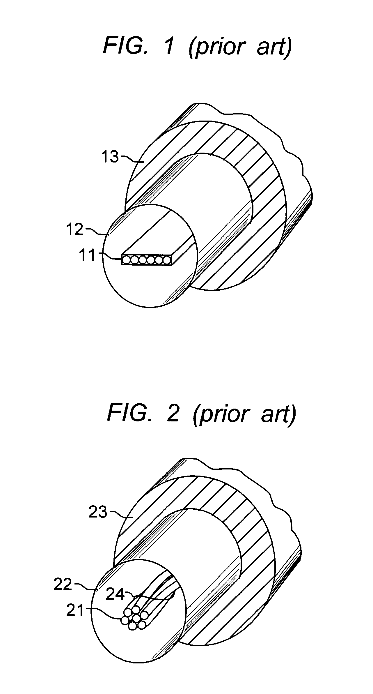
[0024]Referring to FIG. 1, an optical fiber ribbon 11 is shown encased in a cable sheath. The cable sheath comprises tube 12 and tube coating 13. In this illustration, the optical fiber ribbon has six fibers. Ribbons with four or eight fibers and more, are common and commercially available. It will be understood that these numbers are arbitrary for the purpose of illustration. For more details on the structure of optical fiber ribbons see U.S. Pat. No. 4,900,126, which is incorporated by reference herein. In the embodiment of FIG. 1, the optical fiber stack 11 is essentially completely decoupled from the sheath tube 12. This is a so-called “loose tube” assembly, which is designed to allow the optical fiber stack to “float” inside the tube. When small bends or dents occur in the tube they are minimally translated to the optical fibers.

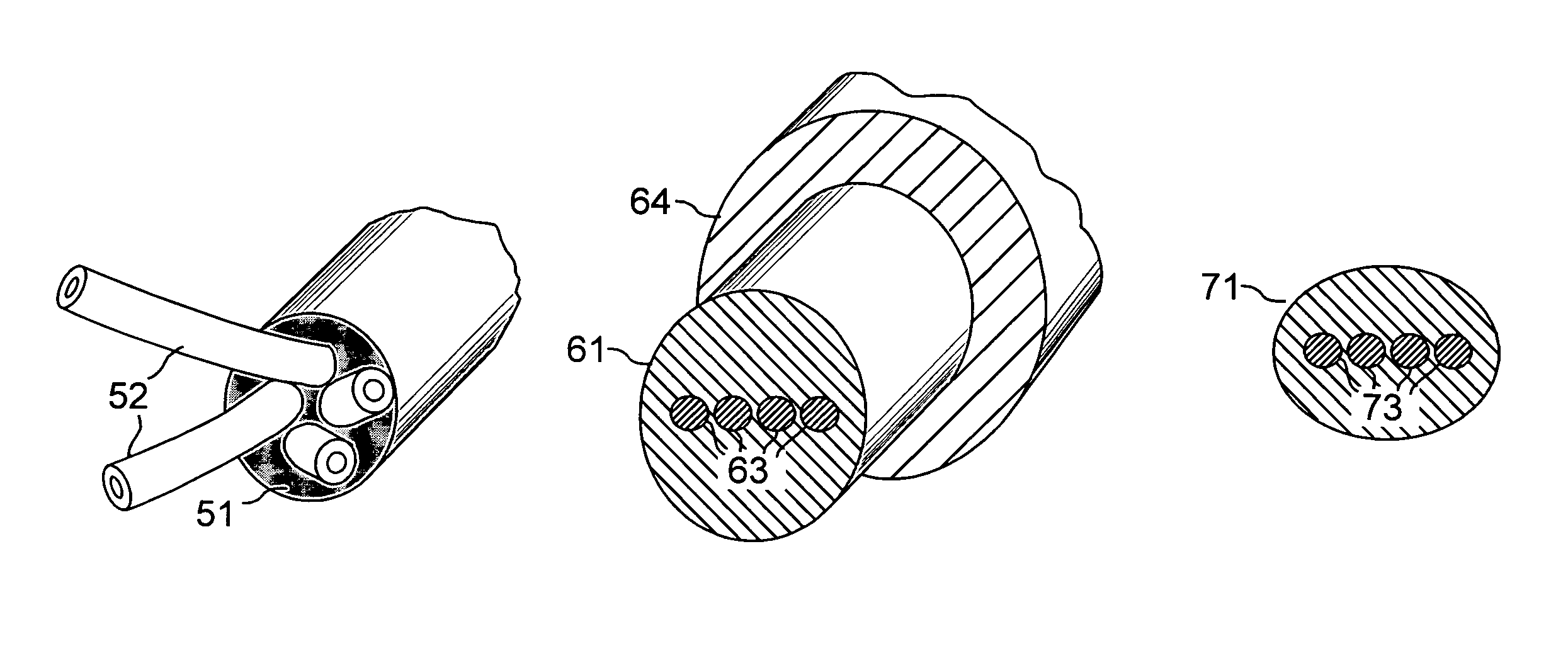
[0025]An alternative optical fiber bundle cable design is shown in FIG. 2. The optical fiber bundle is shown at 21, the tube at 22 and tube coating at ...


PUM


Abstract

The specification describes an improved optical fiber cable wherein the cable cross section is round and contains a plurality of bundled optical fibers. The bundle may comprise randomly spaced fibers or fibers aligned in a ribbon configuration. The bundle is encased in a polymer encasement that couples mechanically to each optical fiber. Preferably, the fibers are spaced from the nearest neighbor to improve coupling. In some embodiments the encasement is relatively hard, and is deliberately made to adhere to the optical fiber bundle. Consequently the encasement medium functions as an effective stress translating medium that deliberately translates stresses on the cable to the optical fibers. The cable construction of the invention is essentially void free, and provides a dry cable with water blocking capability.

Description

RELATED APPLICATIONS[0001]This application claims priority of application Ser. No. 10 / 420,309, filed Apr. 22, 2003 and application Ser. No. 10 / 706,585, filed Nov. 12, 2003.FIELD OF THE INVENTION[0002]This invention relates to optical fiber cables having improved optical transmission characteristics. More particularly, it relates to lightwave transmission cable structures, and methods for their manufacture, in which optical fibers are independently suspended in a coupled encasement to reduce bending losses.BACKGROUND OF THE INVENTION[0003]High capacity lightwave transmission cables frequently comprise multiple optical fibers organized in a ribbon or bundled fiber configuration. Conventional bundled fiber cables typically have two or more optical fibers randomly organized at the cable core. In an effort to increase the optical fiber density and space efficiency, optical fiber ribbons were designed. In this description, optical fiber ribbons are considered as a species of an optical fi...

Claims


Application Information

Patent Timeline
Patent Type & Authority Patents(United States)
IPC IPC(8): G02B6/44
CPCG02B6/443
Inventor BOCANEGRA, LUIS M.DEBBAN, HAROLD P.MEEKS, JENNIFER R.TAYLOR, KENNETH L.WEIMANN, PETER A.
Owner FURAKAWA ELECTRIC NORTH AMERICA INC
Why Eureka
Try Eureka