High effectiveness cooled turbine vane or blade

a turbine blade and high-efficiency technology, applied in the field of turbine blades, can solve the problems of limiting factors in achieving improved power plant efficiency, unable to meet the requirements of high-efficiency turbine blades, and difficult to manufacture, etc., to achieve the effect of reducing cooling flow, facilitating manufacturing, and high cooling efficiency

Inactive Publication Date: 2005-12-13
HONEYWELL INT INC
View PDF31 Cites 179 Cited by
  • Summary
  • Abstract
  • Description
  • Claims
  • Application Information

AI Technical Summary

Benefits of technology

[0012]The present invention provides a robust multiple-walled, multi-pass, high cooling effectiveness cooled turbine vane or blade designed for ease of manufacturability and for affordability. The purpose of this invention is to minimize cooling flows through highly loaded turbine rotors. It could also be used and retrofitted into current production engines. The inventive vane or blade design allows the turbine inlet temperature to increase by about 600° F. over conventional technology levels while simultaneously reducing turbine cooling to low levels that are not possible using the prior art. The reduction in cooling flow is equivalent to an improvement in specific fuel consumption of about 1.0% from this component alone.
[0013]The invention comprises a sophisticated multi-wall cooling system that meets the inherent conflict to maximize the flow area of the cooling passages while retaining the required section thickness to meet the structural requirements. A unique feature of the present invention is the independent cooling circuits for the blade's pressure and suction surfaces. This unique strategy

Problems solved by technology

The turbine vanes and blades lie at the heart of the power plant, and it is well established that, in most cases, they are one of the limiting factors in achieving improved power plant efficiency.
The concept of a multi-walled turbine vane or blade has been discussed for many years with attempts proving to be extremely costly to fabricate.
In fact, it is not always desirable to have flow through the center body core cavity, because a no/low flow condition in the center body core means a very low heat transfer coefficient for the inner cool wall.
This does not allow independent, optimized cooling for the pressure and suction sides in

Method used


Image

  • High effectiveness cooled turbine vane or blade
  • High effectiveness cooled turbine vane or blade
  • High effectiveness cooled turbine vane or blade

Examples


Embodiment Construction

[0036]The following detailed description is of the best currently contemplated modes of carrying out the invention. The description is not to be taken in a limiting sense, but is made merely for the purpose of illustrating the general principles of the invention, since the scope of the invention is best defined by the appended claims.

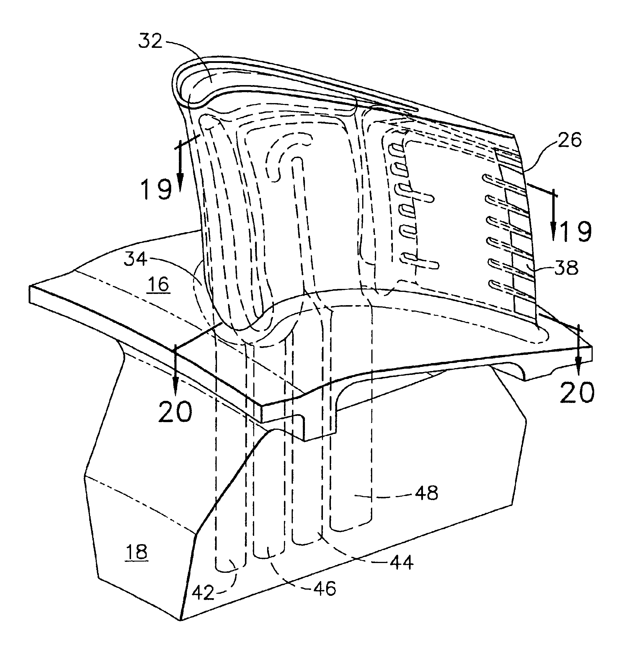
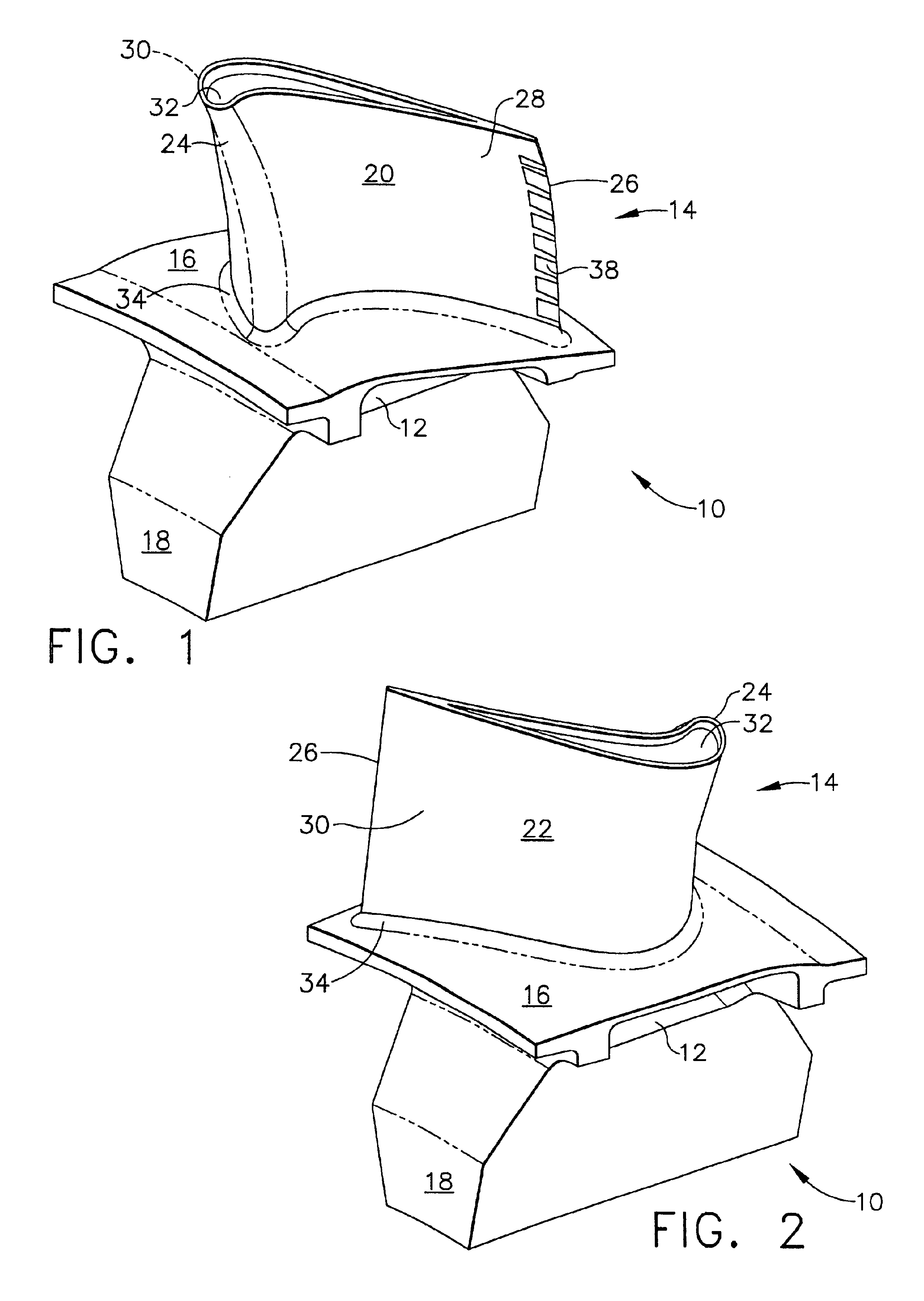
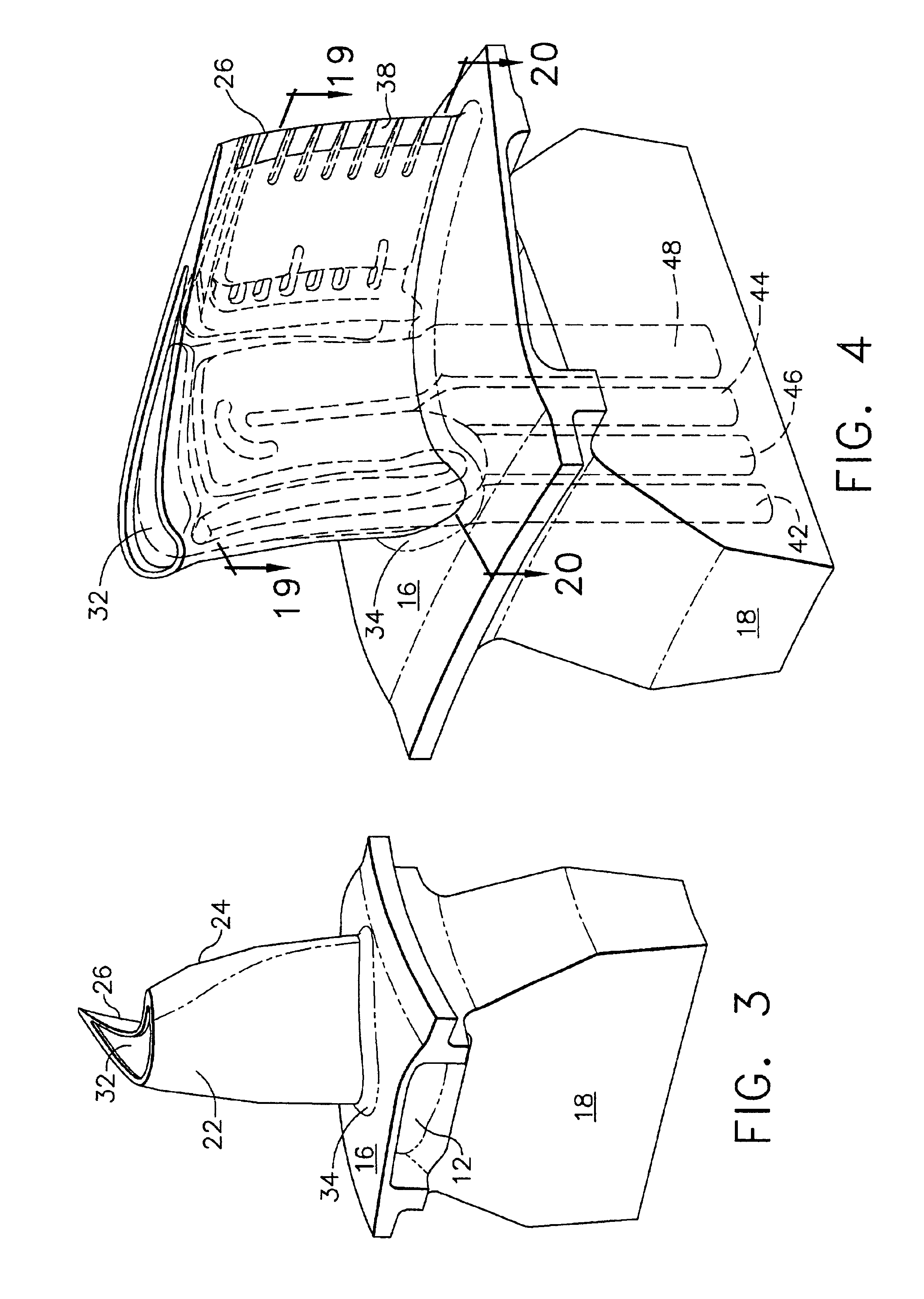
[0037]FIGS. 1, 2 and 3 disclose an aircraft jet engine turbine rotor blade 10 that includes a shank 12 and the airfoil 14 of the invention. The shank 12 includes a platform 16, which helps to radially contain the turbine airflow, and a blade root area 18 where the dovetail (not shown) would be machined, which in the case of the blade attaches it to a turbine rotor disc (not shown). The airfoil blade 14 has a first outer wall 20 a second outer wall 22 together defining an airfoil shape including a leading edge 24, a trailing edge 26, a pressure side 28 along the first outer wall 20, a suction side 30 along the second outer wall 22, a blade tip 32, a pres...


PUM


Abstract

A robust multiple-walled, multi-pass, high cooling effectiveness cooled turbine vane or blade designed for ease of manufacturability, minimizes cooling flows on highly loaded turbine rotors. The vane or blade design allows the turbine inlet temperature to increase over current technology levels while simultaneously reducing turbine cooling to low levels. A multi-wall cooling system is described, which meets the inherent conflict to maximize the flow area of the cooling passages while retaining the required section thickness to meet the structural requirements. Independent cooling circuits for the vane or blade's pressure and suction surfaces allow the cooling of the airfoil surfaces to be tailored to specific heat load distributions (that is, the pressure surface circuit is an independent forward flowing serpentine while the suction surface is an independent rearward flowing serpentine). The cooling air for the independent circuits is supplied through separate passages at the base of the vane or blade. The cooling air follows intricate passages to feed the serpentine thin outer wall passages, which incorporate pin fins, turbulators, etc. These passages, while satisfying the aero/thermal/stress requirements, are of a manufacturing configuration that may be cast with single crystal materials using conventional casting techniques.

Description

BACKGROUND OF THE INVENTION[0001]The present invention generally relates to turbine vanes and blades and, more particularly, to high temperature turbine vanes and blades designed for high effectiveness cooling and ease of manufacture.[0002]Gas turbine power plants are used as the primary propulsive power source for aircraft, in the forms of jet engines and turboprop engines, as auxiliary power sources for driving air compressors, hydraulic pumps, etc. on aircraft, and as stationary power supplies such as backup electrical generators for hospitals and the like. The same basic power generation principles apply for all of these types of gas turbine power plants. Compressed air is mixed with fuel and burned, and the expanding hot combustion gases are directed against stationary turbine vanes in the engine. The vanes turn the high velocity gas flow to impinge upon turbine blades mounted on a turbine disk or wheel that is free to rotate.[0003]The force of the impinging gas causes the turb...

Claims


Application Information

Patent Timeline
IPC IPC(8): F01D5/18
CPCB22C9/04B22C9/103F01D5/187Y02T50/673Y02T50/676F05D2230/21F05D2260/202F05D2260/22141Y02T50/60
Inventor HALFMANN, STEVE H.KIM, YONG W.MORRIS, MARK C.ORTIZ, MILTONPACK, DAVID R.WILSON, CRAIG A.
Owner HONEYWELL INT INC
Why Eureka
Try Eureka