Control system for a linear vibration motor

a technology of linear vibration and control system, which is applied in the direction of motor/generator/converter stopper, dynamo-electric converter control, instruments, etc., can solve the problems of plastic deformation and breakage of the support spring, the mover and the motor body, etc., to reduce the driving frequency, reduce friction loss, and seal the effect of the refrigeran

Inactive Publication Date: 2005-12-20
PANASONIC CORP
View PDF13 Cites 32 Cited by
  • Summary
  • Abstract
  • Description
  • Claims
  • Application Information

AI Technical Summary

Benefits of technology

[0035]To be specific, even when the actual motor output is not equal to the required motor output, the linear vibration motor can be efficiently driven at the resonance frequency until the actual motor output reaches the maximum output at which driving of the linear vibration motor at the resonance frequency is restricted by the voltage level of the power supply. Further, in a high output region where the actual motor output of the linear vibration motor that is driven at the resonance frequency exceeds the maximum output, the linear vibration motor can be driven at a frequency which is higher than the resonance frequency, without significantly reducing the driving frequency. Moreover, in the high output region, the driving frequency is set at a frequency which is closest to the resonance frequency, at which the required motor output can be generated, whereby the driving frequency can be smoothly returned to the resonance frequency when the required motor output is decreased.
[0036]According to a twelfth aspect of the present invention, there is provided an air conditioner which is equipped with a compressor that has a cylinder and a piston, and compresses a fluid in the cylinder by a reciprocating motion of the piston. The air conditioner also includes: a linear vibration motor for making the piston reciprocate, where the linear vibration motor has a stator and a mover, which is supported by a spring so as to form a spring vibration system including the mover; and a motor driving unit for driving the linear vibration motor, which motor driving unit is a motor driving apparatus as defined in any one of the first through eleventh aspects. Therefore, friction loss can be reduced as compared with a conventional rotation-type motor, and further, sealability of the refrigerant between the high-pressure side and the low-pressure side is increased, whereby efficiency of the compressor is enhanced. Moreover, since friction loss is reduced, the amount of lubricating oil that is indispensable in the rotation-type motor can be significantly reduced. Thereby, recyclability is enhanced, and the amount of refrigerant to be filled in the compressor is reduced because the amount of refrigerant that dissolves into the oil is reduced, which results in a contribution to the conservation of the global environment. Further, since the performance of the linear compressor is controlled by the driving frequency, the linear compressor can be driven at maximum performance without being restricted by its construction, whereby a design that provides maximum efficiency at rated performance can be carried out. As a result, the air conditioner using the linear compressor can be reduced in size and increased in efficiency.
[0037]According to a thirteenth aspect of the present invention, there is provided a refrigerator which is equipped with a compressor that has a cylinder and a piston, and compresses a fluid in the cylinder by a reciprocating motion of the piston. The refrigerator also includes: a linear vibration motor for making the piston reciprocate, where the linear vibration motor has a stator and a mover, which is supported by a spring so as to form a spring vibration system including the mover; and a motor driving unit for driving the linear vibration motor, which motor driving unit is a motor driving apparatus as defined in any one of the first through eleventh aspects. Therefore, friction loss can be reduced as compared with a conventional rotation-type motor, and further, sealability of the refrigerant between the high-pressure side and the low-pressure side is increased, whereby efficiency of the compressor is enhanced. Moreover, since friction loss is reduced, the amount of lubricating oil that is indispensable in the rotation-type motor can be significantly reduced. Thereby, recyclability is enhanced, and the amount of refrigerant to be filled in the compressor is reduced because the amount of refrigerant that dissolves into the oil is reduced, which results in a contribution to the conservation of the global environment. Further, since performance the of the linear compressor is controlled by the driving frequency, the linear compressor can be driven at maximum performance without being restricted by the construction, whereby design that provides maximum efficiency at rated performance can be carried out. As a result, the refrigerator using the linear compressor can be reduced in size and increased in efficiency.
[0038]According to a fourteenth aspect of the present i

Problems solved by technology

In the linear vibration motor, however, when the stroke length of the mover becomes larger than a predetermined allowable value, a problem such as a collision between the mover and the motor body or a breakage of the support spring may occur.
For example, when the extension of the support spring exceeds a predetermined value due to an increase in the stroke length of the mover, the support spring may plastically deform and break.
Further, when the stroke length of the mover is increased to about the size of the motor body in the mover vibrating direction, the mover may collide against the inner wall of the motor body and break.
As a result, the maximum output of the linear vibration motor is undesirably restricted by the structure of the linear vibration motor, and further, the maximum output of the linear vibration motor is undesirably restricted by the power supply voltage which is applied to the motor driving apparatus.
Accordingly, in the conventional linear vibration motor, the mechanical construction is determined based the required maximum output, and therefore, an increase in the maximum output may lead to not only an in

Method used


Image

  • Control system for a linear vibration motor
  • Control system for a linear vibration motor
  • Control system for a linear vibration motor

Examples


first embodiment

[0056

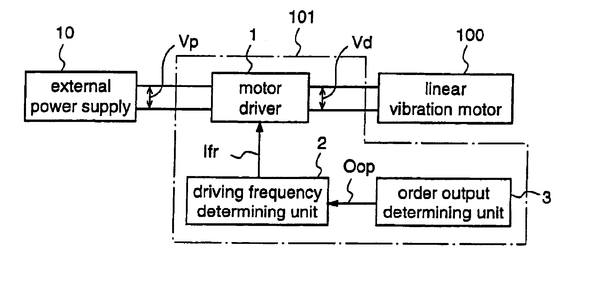
[0057]FIG. 1 is a block diagram for explaining a motor driving apparatus according to a first embodiment of the present invention.

[0058]A motor driving apparatus 101 according to the first embodiment drives a linear vibration motor 100, which has a stator, a mover, and a support spring that supports the mover so as to form a spring vibration system including the mover, at a driving frequency according to a required motor output. The stator comprises an electromagnet which is obtained by winding a coil around an iron core, and the mover comprises a permanent magnet.

[0059]More specifically, the motor driving apparatus 101 includes an order output determining unit 3 for determining a target output that is a motor output which is required of the linear vibration motor 100, and outputting an output order signal Oop indicating the determined target output.

[0060]Further, the motor driving apparatus 101 includes a driving frequency determining unit 2 for determining a driving frequency...

second embodiment

[0077

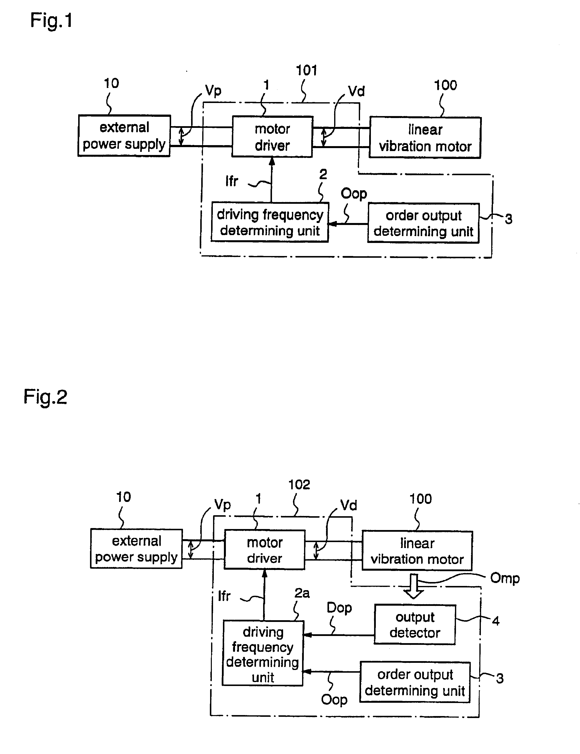
[0078]FIG. 2 is a block diagram for explaining a motor driving apparatus according to a second embodiment of the present invention.

[0079]A motor driving apparatus 102 according to the second embodiment drives a linear vibration motor 100, which has a stator, a mover, and a support spring that supports the mover so as to form a spring vibration system including the mover, while adjusting the driving frequency so as to reduce a difference between the motor output and a desired motor output. The linear vibration motor 100 according to this second embodiment is identical to that of the first embodiment.

[0080]More specifically, the motor driving apparatus 102 includes an order output determining unit 3 for determining a target output that is a motor output which is required of the linear vibration motor 100 so as to output an output order signal Oop indicating the determined target output. The motor driving apparatus 102 also includes an output detector 4 for detecting a motor outpu...

third embodiment

[0098

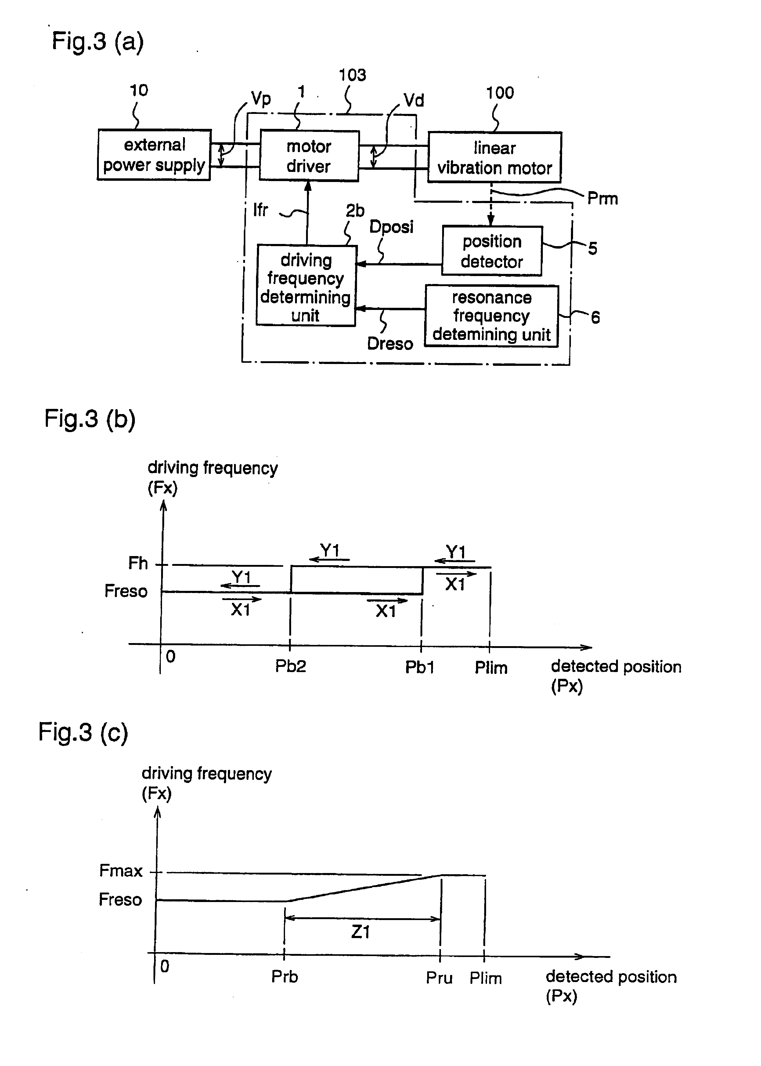
[0099]FIG. 3(a) is a block diagram for explaining a motor driving apparatus according to a third embodiment of the present invention.

[0100]A motor driving apparatus 103 according to the third embodiment drives a linear vibration motor 100, which has a stator, a mover, and a support spring that supports the mover so as to form a spring vibration system including the mover, at a driving frequency that is determined based on the position of the mover. The linear vibration motor 100 of this third embodiment is identical to that of the first embodiment.

[0101]To be specific, the motor driving apparatus 103 includes: a position detector 5 for detecting the position of the reciprocating mover, and outputting a position detection signal Dposi indicating the detected mover position; a resonance frequency determining unit 6 for outputting a resonance frequency signal Dreso indicating the resonance frequency of the linear vibration motor 100; a driving frequency determining unit 2b for det...


PUM


Abstract

A motor driving apparatus for driving a linear vibration motor includes an order output determining unit for determining a motor output which is required of the linear vibration motor, and a driving frequency determining unit for determining a driving frequency of the linear vibration motor based on the determined motor output. An amplitude-fixed AC voltage having a frequency which is equal to the determined driving frequency is applied to the linear vibration motor, whereby the output of the linear vibration motor can be controlled without changing the amplitude value of the driving voltage which is applied to the linear vibration motor.

Description

TECHNICAL FIELD[0001]The present invention relates to motor driving apparatuses and, more particularly, to a motor driving apparatus for driving a linear vibration motor having a mover and a spring member for supporting the mover.BACKGROUND ART[0002]Conventional equipment using linear vibration motors include vibration generators for informing of incoming calls by mechanical vibration, handy phones including such vibration generators, compressors for compressing and circulating gases or fluids, and reciprocating electric razors. The compressors and electric razors use the linear vibration motors as their driving sources.[0003]A typical linear vibration motor has a structure of a single-phase sync motor. That is, the typical linear vibration motor it has a mover comprising a permanent magnet and a stator which is obtained by winding a coil around an iron core, and the mover reciprocates when an AC voltage is applied to the coil.[0004]As described above, when generating vibration by a...

Claims


Application Information

Patent Timeline
IPC IPC(8): B26B19/28B26B19/38F24H4/00F25B1/02F25B13/00H02K33/16H02P25/02
CPCB26B19/282B26B19/38B26B19/388F24H4/00F25B1/02F25B13/00F25B2400/073H02K33/16H02P25/032H02P25/00G05D19/02
Inventor UEDA, MITSUONAKATA, HIDEKIYOSHIDA, MAKOTO
Owner PANASONIC CORP
Why Eureka
Try Eureka