Clock and data recovery phase-locked loop

a phase-locked loop and clock technology, applied in the field of communication systems, can solve the problems of high clock speed limiting the usefulness of prior art clock recovery circuits, substantially increasing manufacturing costs, and limiting prior art designs

Active Publication Date: 2005-12-20
XILINX INC
View PDF6 Cites 15 Cited by
  • Summary
  • Abstract
  • Description
  • Claims
  • Application Information

AI Technical Summary

Benefits of technology

[0012]The preferred embodiment of the invention uses a delay insensitive architecture that do

Problems solved by technology

Higher clock speeds limit the usefulness of prior art clock recovery circuits that require precise alignment of signals to recover clock and/or data.
Some prior art designs are bandwidth limited.
For instance, switching from a CMOS process to a silicon germanium or gallium arsenide process would allo

Method used


Image

  • Clock and data recovery phase-locked loop
  • Clock and data recovery phase-locked loop
  • Clock and data recovery phase-locked loop

Examples


Embodiment Construction

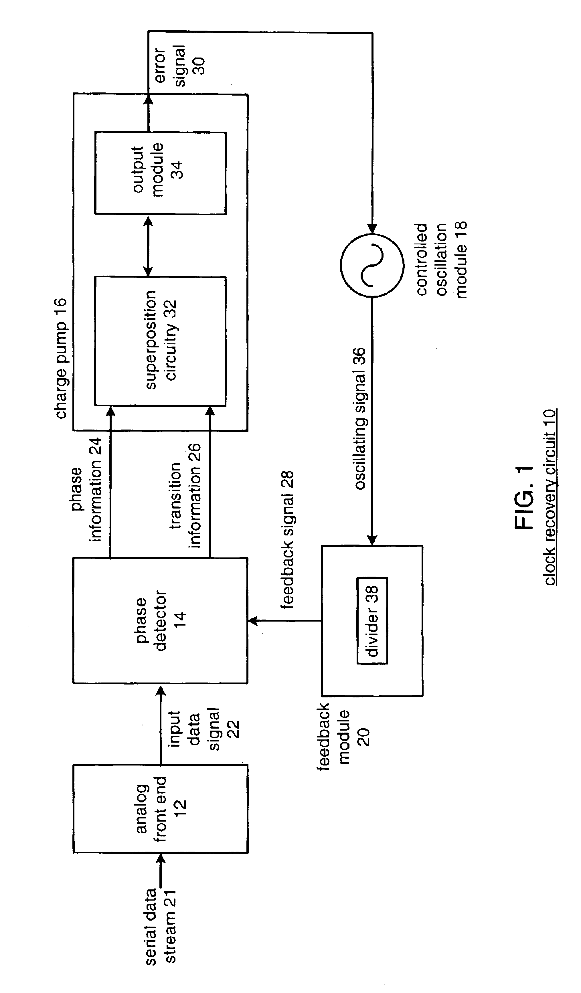
[0024]FIG. 1 illustrates a block diagram of a clock and / or data recovery circuit 10 in accordance with the preferred embodiment of the present invention. The clock recovery circuit 10 includes an analog front end 12, a phase detector 14, a charge pump 16, a controlled oscillation module 18, and a feedback module 20. Charge pump 16 includes superposition circuitry 32 and an output module 34.

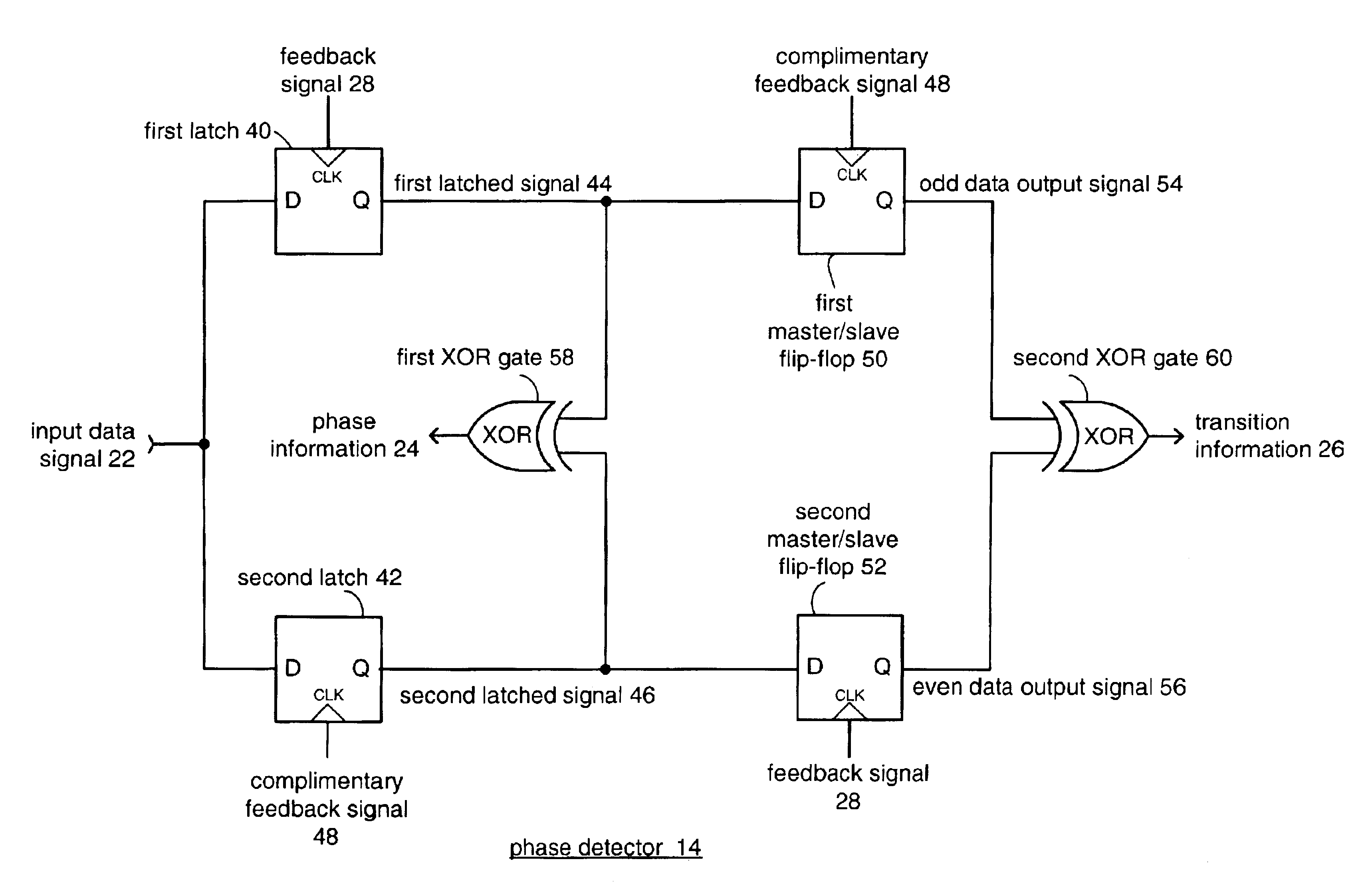
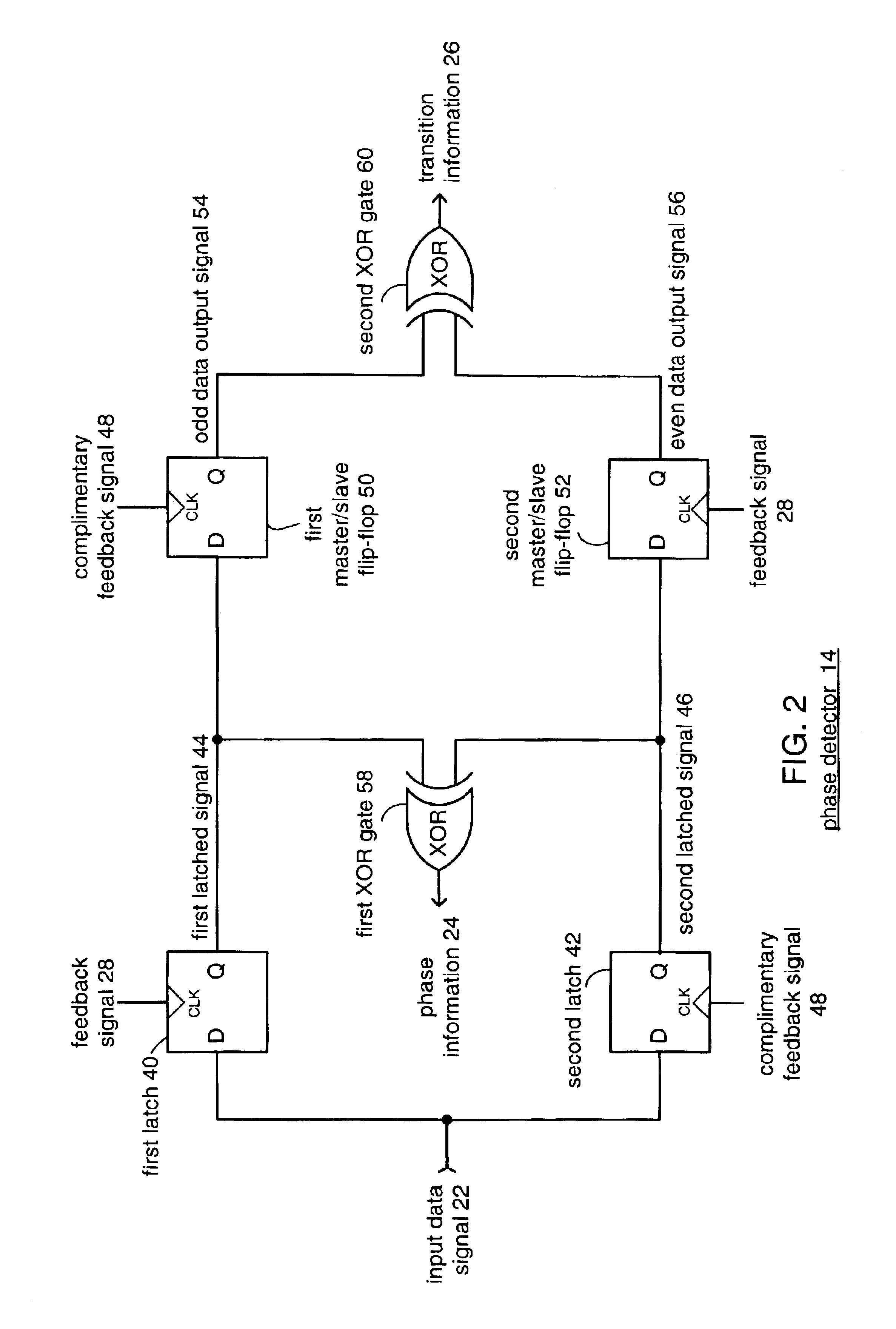
[0025]Analog front end 12 receives a serial data stream 21, which may be a high data rate bit stream transferring data at 10 or more gigabits per second. This high data rate usually results in some loss of high frequency components of the bit stream due to the limited bandwidth of the input line. Analog front end 12 provides amplitude equalization to produce input data signal 22. Phase detector 14 produces phase information 24 and transition information 26 based on the input data signal 22 and a feedback signal 28. Operation of phase detector 14 will be discussed in greater detail with reference t...


PUM


Abstract

A clock recovery circuit that operates at a clock speed equal to one-half the input data rate is presented. The clock recovery circuit uses dual input latches to sample the incoming serial data on both the rising edge and falling edge of a half-rate clock signal to provide equivalent full data rate clock recovery. The clock recovery circuit functions to maintain the half-rate clock transitions in the center of the incoming serial data bits. The clock recovery circuit includes a phase detector, charge pump, controlled oscillation module and a feedback module. The phase detector produces information on the phase and data transitions in the incoming data signal to the charge pump. Generally, the circuit is delay insensitive and receives phase and transition information staggered relative to each other.

Description

BACKGROUND OF THE INVENTION[0001]1. Technical Field[0002]This invention relates generally to communication systems and more particularly to clock recovery circuits used therein.[0003]2. Description of Related Art[0004]Communication systems are known to transport large amounts of data between a plurality of end user devices, which, for example, include telephones, facsimile machines, computers, television sets, cellular telephones, personal digital assistants, etc. As is also known, such communication systems may be local area networks (LANs) and / or wide area networks (WANs) that are stand-alone communication systems or interconnected to other LANs and / or WANs as part of a public switched telephone network (PSTN), packet switched data network (PSDN), integrated service digital network (ISDN), or Internet. As is further known, communication systems include a plurality of system equipment to facilitate the transporting of data. Such system equipment includes, but is not limited to, rou...

Claims


Application Information

Patent Timeline
IPC IPC(8): H03D13/00H03L7/087H03L7/089H03L7/10H04L7/033
CPCH03D13/003H03L7/087H03L7/091H03L7/10H04L7/0331H03L7/0896H03L7/113
Inventor BRUNN, BRIAN T.YOUNIS, AHMEDROKHSAZ, SHAHRIAR
Owner XILINX INC
Why Eureka
Try Eureka