Nitrogen rejection from condensed natural gas

a technology of condensed natural gas and nitrogen, which is applied in the direction of gaseous fuels, liquefaction, lighting and heating apparatus, etc., can solve the problems of reducing the options for disposing of rejected nitrogen, unable to vent the nitrogen stream, and generating fuel gas streams in the final steps of the liquefaction process. , to achieve the effect of reducing the pressure of the condensed natural gas prior to the distillation column

Inactive Publication Date: 2005-12-27
AIR PROD & CHEM INC
View PDF28 Cites 22 Cited by
  • Summary
  • Abstract
  • Description
  • Claims
  • Application Information

AI Technical Summary

Benefits of technology

[0044](e) cooling a second portion of the cooled compressed nitrogen-rich stream by indirect heat exchange with the nitrogen-enriched overhead vapor stream from the distillation column and the cold nitrogen-rich refrigerant stream to provide a cold compressed nitrogen-rich stream, reducing the pressure of the cold compressed nitrogen-rich stream to provide a reduced-pressure cold nitrogen-rich stream, and introducing the reduced-pressure cold nitrogen-rich stream into the distillation column as the cold reflux stream.
[0045]The pressure of the condensed natural gas prior to the distillation column may be reduced by passing the cooled liquefied natural gas feed through a dense-fluid expander.

Problems solved by technology

Some of these constituents, such as water, hydrogen sulfide, carbon dioxide, and mercury, are contaminants which are harmful to downstream steps such as natural gas processing or the production of liquefied natural gas (LNG), and these contaminants must be removed upstream of these processing steps.
Depending on the nitrogen rejection process, the rejected nitrogen still may contain a significant concentration of methane, and if so, this rejected nitrogen stream cannot be vented and must be sent to the plant fuel system.
In certain LNG operations, the generation of fuel gas streams in the final steps of the liquefaction process may be undesirable.
This reduces available options for disposing of rejected nitrogen, since venting is possible only if the rejected nitrogen contains low concentrations of methane, for example, below about 5 mole %.

Method used


Image

  • Nitrogen rejection from condensed natural gas
  • Nitrogen rejection from condensed natural gas
  • Nitrogen rejection from condensed natural gas

Examples


example

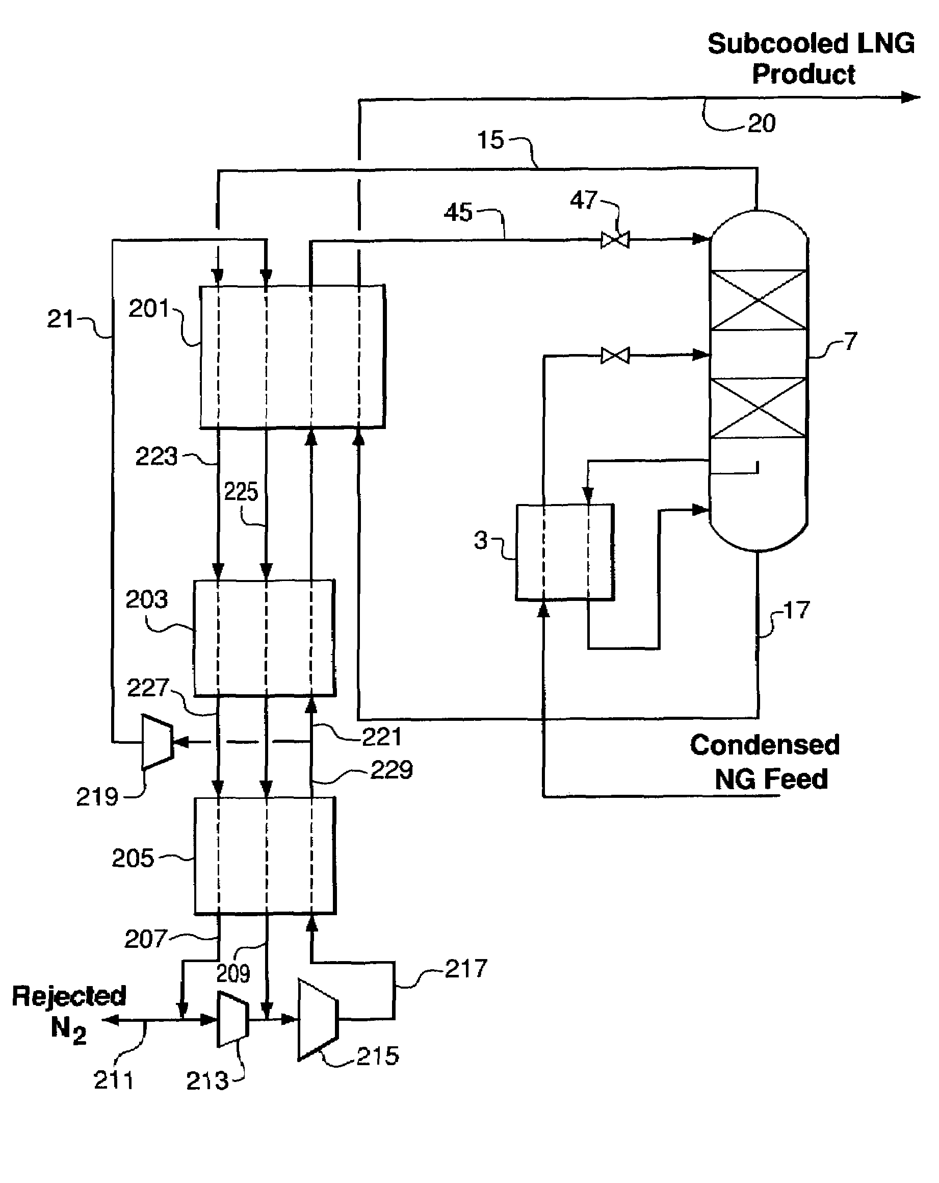
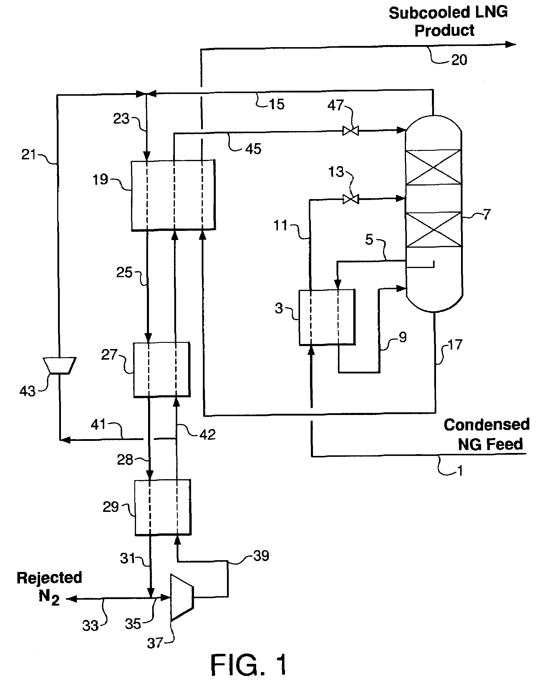
[0116]An embodiment of the invention as described with reference to FIG. 1 may be illustrated by the following non-limiting Example. A condensed natural gas feed stream at a flow rate of 100 lbmoles per hour containing (in mole %) 4.0% nitrogen, 88.0% methane, 5.0% ethane and 3.0% propane and heavier hydrocarbons at −165° F. and 741 psia is provided via line 1 and is cooled to −190° F. in the reboiler heat exchanger 3. The cooled LNG feed stream in line 11 from the reboiler is flashed across expansion valve 13 to 144 psia and introduced at an intermediate location into distillation column 7. A purified LNG product stream is withdrawn via line 17 at a flow rate of 96.94 lbmoles per hour containing (in mole %) 1.00% nitrogen, 90.75% methane, 5.16% ethane and 3.09% propane and heavier hydrocarbons at −190° F. and 147 psia. This LNG product stream is subcooled to −235° F. in heat exchanger 19 and sent to storage via line 20.

[0117]A nitrogen-rich overhead vapor stream is withdrawn from d...


PUM


Abstract

Method for the rejection of nitrogen from condensed natural gas which comprises (a) introducing the condensed natural gas into a distillation column at a first location therein, withdrawing a nitrogen-enriched overhead vapor stream from the distillation column, and withdrawing a purified liquefied natural gas stream from the bottom of the column; (b) introducing a cold reflux stream into the distillation column at a second location above the first location, wherein the refrigeration to provide the cold reflux stream is obtained by compressing and work expanding a refrigerant stream comprising nitrogen; and (c) either (1) cooling the purified liquefied natural gas stream or cooling the condensed natural gas stream or (2) cooling both the purified liquefied natural gas stream and the condensed natural gas stream, wherein refrigeration for (1) or (2) is obtained by compressing and work expanding the refrigerant stream comprising nitrogen. The refrigerant stream may comprise all or a portion of the nitrogen-rich vapor stream from the distillation column.

Description

BACKGROUND OF THE INVENTION[0001]Raw natural gas contains primarily methane and also includes numerous minor constituents such as water, hydrogen sulfide, carbon dioxide, mercury, nitrogen, and light hydrocarbons typically having two to six carbon atoms. Some of these constituents, such as water, hydrogen sulfide, carbon dioxide, and mercury, are contaminants which are harmful to downstream steps such as natural gas processing or the production of liquefied natural gas (LNG), and these contaminants must be removed upstream of these processing steps. After these contaminants are removed, the hydrocarbons heavier than methane are condensed and recovered as natural gas liquids (NGL) and the remaining gas, which comprises primarily methane, nitrogen, and residual light hydrocarbons, is cooled and condensed to yield a final LNG product.[0002]Because crude natural gas may contain 1–10 mole % nitrogen, removal of nitrogen is necessary in many LNG production scenarios. A nitrogen rejection ...

Claims


Application Information

Patent Timeline
Patent Type & Authority Patents(United States)
IPC IPC(8): F25J3/08F25J3/02
CPCC10L3/10F25J3/0209F25J3/0233F25J3/0257F25J2200/02F25J2200/50F25J2200/74F25J2200/76F25J2205/04F25J2215/04F25J2240/12F25J2240/30F25J2270/04F25J2270/08F25J2270/12F25J2270/14F25J2270/42Y10S62/927F25J3/02F25J3/08
Inventor BROSTOW, ADAM ADRIANROBERTS, MARK JULIANSPILSBURY, CHRISTOPHER GEOFFREY
Owner AIR PROD & CHEM INC
Why Eureka
Try Eureka