System and method for generation of electricity and power from waste heat and solar sources

a technology of waste heat and solar energy, applied in the field of power generation, can solve the problems of increasing the cost of operation, and generating a large amount of waste heat daily, and achieves the effects of convenient skid mounting, simple site installation and operation setup, and simple installation

Inactive Publication Date: 2006-01-03
OUTFITTER ENERGY
View PDF11 Cites 133 Cited by
  • Summary
  • Abstract
  • Description
  • Claims
  • Application Information

AI Technical Summary

Benefits of technology

[0019]The system is an ORC (Organic Rankin Cycle) system, in that it operates at lower pressure, typically 100–150 psig on the input side of the expander and 4–5″ vacuum on the output side of the expander. The inventive system can be sized to the heat source, and is conveniently skid-mountable so that the system can be provided as a factory-made, modular, shippable unit for simple installation and hook up at a customer site. In such a modular unit form, a unit of the inventive system includes: a PLC or other type of controller, sensors, piping, valves, pumps, expander, generator, oil separator (if required for an oil loop lubricated expander) condenser, bypass and receiver, flanges for connection of the refrigerant pressurized inlet to the heat exchanger and outlet to the expander and flanges for connection to a beat sink for the condenser. The condenser heat sink is preferably a cooling tower that is provided as part of the inventive system on a separate skid, or may be a local, pre-existing cooling tower or other heat sink. Likewise, a heat exchanger can be supplied on a separate skid with flanges for connection of the waste or solar heat fluid source inlets and outlets to the heat exchanger, and the inlet from the system refrigerant pump and the outlet to the expander. Thus, typically the inventive system is provided in pre-manufactured modules of from 1–3 skid-mounted units having mating connections for simple site installation and operational set-up.

Problems solved by technology

Currently, enormous amounts of waste heat are generated daily by a wide variety of industrial and commercial processes and operations.
Typically, the waste heat is low grade, that is, it is below about 350° F., and often below about 250° F., a value so low that conventional heat recovery systems do not operate with sufficient efficiency to make recovery of energy from such sources economical.
The net result is that vast quantities of waste heat are simply dumped to atmosphere, ground or water thereby contributing to the overall greenhouse effect and effectively raising the cost of operations.
Except for low efficiency photovoltaic cells, solar energy systems produce hot gases or fluids of maximum temperatures well below the range needed to function as power sources.

Method used


Image

  • System and method for generation of electricity and power from waste heat and solar sources
  • System and method for generation of electricity and power from waste heat and solar sources
  • System and method for generation of electricity and power from waste heat and solar sources

Examples


Embodiment Construction

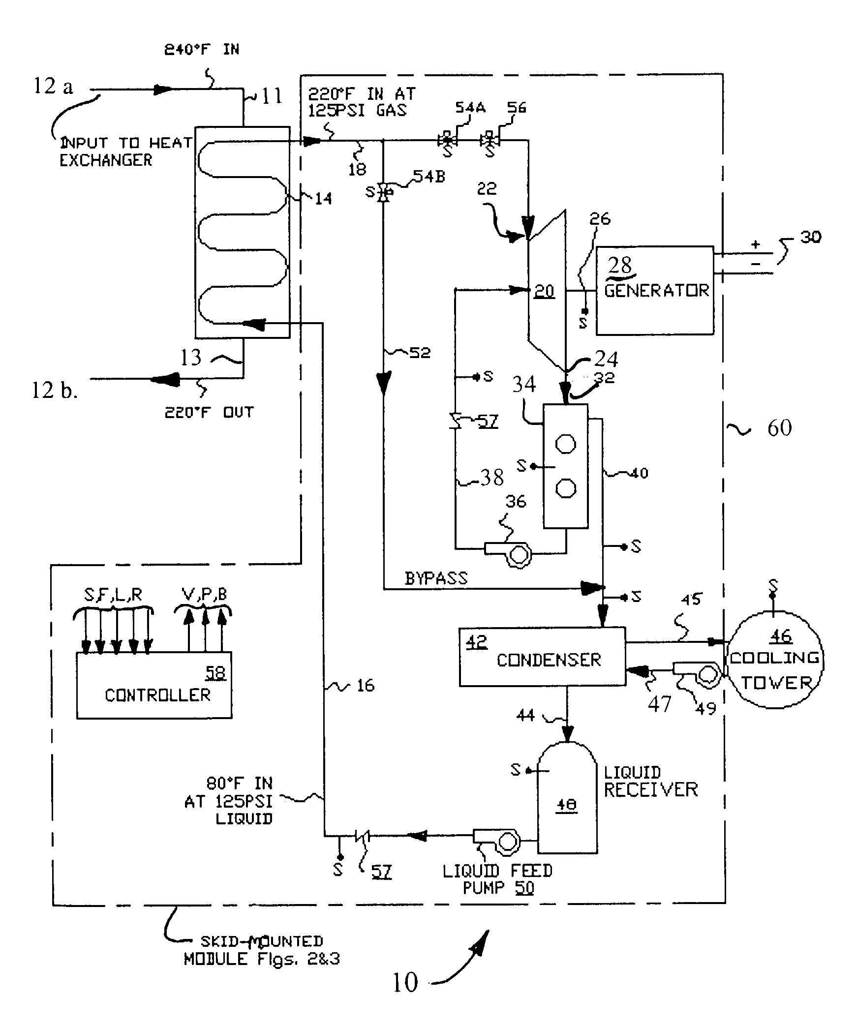
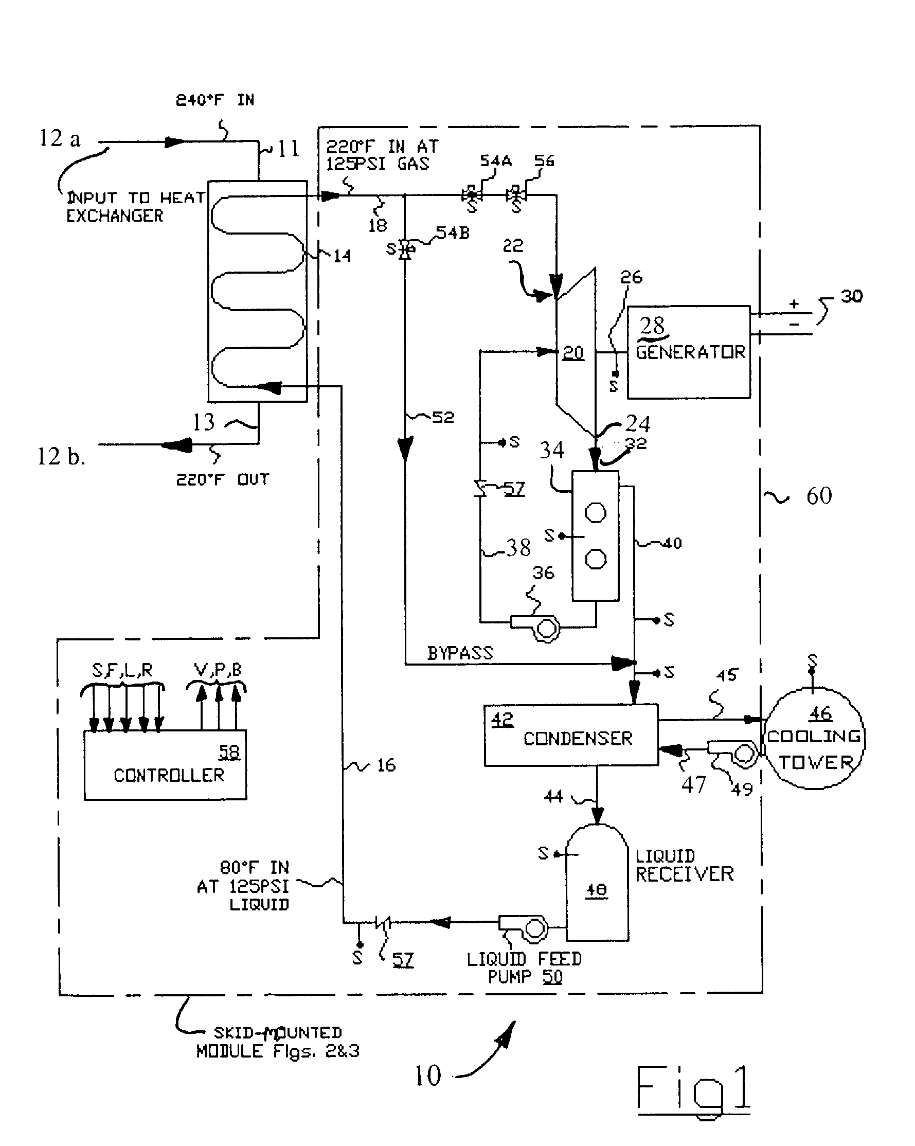
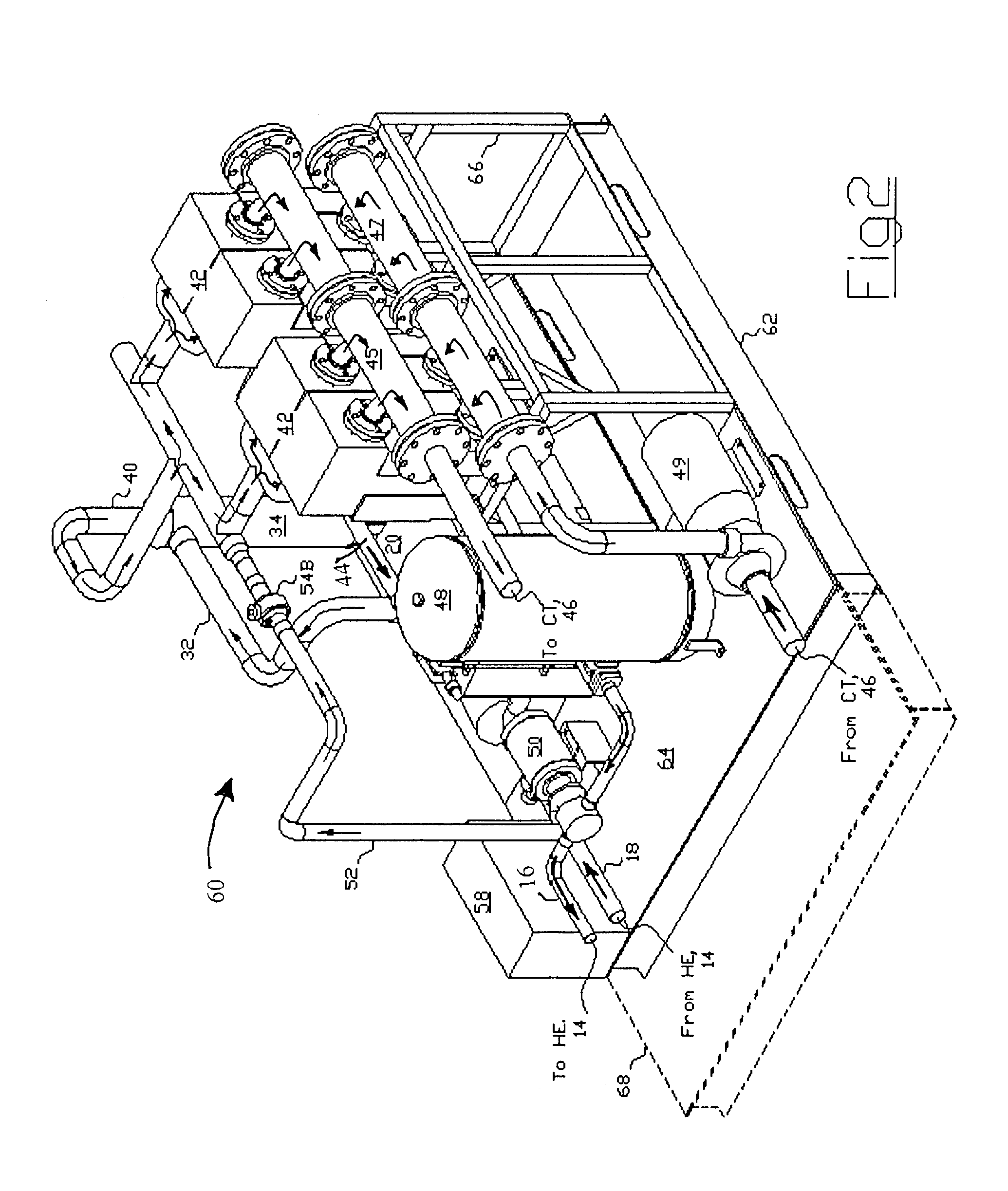
[0034]The following detailed description illustrates the invention by way of example, not by way of limitation of the principles of the invention. This description will clearly enable one skilled in the art to make and use the invention, and describes several embodiments, adaptations, variations, alternatives and uses of the invention, including what are presently believed to be the best modes of carrying out the invention.

[0035]The invention is illustrated in the several figures, and is of sufficient complexity that the many parts, interrelationships, and sub-combinations thereof simply cannot be fully illustrated in a single patent-type drawing. For clarity and conciseness, several of the drawings show in schematic, or omit, parts that are not essential in that drawing to a description of a particular feature, aspect or principle of the invention being disclosed. Thus, the best mode embodiment of one feature may be shown in one drawing, and the best mode of another feature will be...


PUM


Abstract

Recovery of electric power from low-grade waste heat/solar energy, comprising a closed-cycle charged refrigerant loop. Pressurized refrigerant fluid is pumped at ambient temperature through a heat exchanger connected to a waste heat/solar source to extract heat energy during conversion to a high pressure gas. Heated/pressurized refrigerant gas is inlet into an expander to power an output shaft during the expansion of the fluid to a cooled gas at approximately 0 psig. Cooled gaseous refrigerant is condensed to a liquid at low pressure and ambient temperature, and recycled under pressure to the heat exchanger. The expander is a reverse-plumbed gas compressor; the pressurized, hot refrigerant gas is inlet at what is ordinarily its outlet, and the normal inlet becomes the expander end. The refrigerant gas mass flow pressure/temperature drop spins the expander shaft for direct mechanical power take-off, or coupling to a synchronous or inductive generator to produce electricity.

Description

CROSS-REFERENCE TO RELATED APPLICATION[0001]This is the Regular US and PCT Application of Provisional U.S. Ser. No. 60 / 360,072 filed Feb. 25, 2002, the priority of which is claimed under 35 US Code § 119.FIELD OF THE INVENTION[0002]The invention relates to the field of power generation, both direct mechanical and electrical, from waste heat sources, and more particularly to the generation of power from low-grade waste combustion or process heat and solar energy sources. The inventive power generation system and method is realized in the preferred embodiment as a modular, skid-mounted system, but may also be adapted for permanent installation for stationary power generation in association with an industrial or commercial installation. The inventive system employs, as a non-limiting example, recovery of energy from waste heat sources by means of circulation of a working fluid (refrigerant) in a closed loop system wherein drop in pressure is through an expander unit having a power take...

Claims


Application Information

Patent Timeline
Patent Type & Authority Patents(United States)
IPC IPC(8): B60K16/00F01K25/00F01K25/08F02G5/00F03G6/00
CPCF01K25/08Y02E20/14Y02E10/46B60K16/00B60K2016/003
Inventor VAYNBERG, MIKHAILHORN, HANS GUNTERHORN, RALFWEILAND, ALFONSAZEVEDO, RICHARD A.
Owner OUTFITTER ENERGY
Why Eureka
Try Eureka