Roller bearing cage
a roller bearing and cage technology, applied in the direction of connecting rod bearings, bearing components, shafts and bearings, etc., can solve the problems of lubricating oil, affecting the precision control of the chamfering area, and imposing harsh conditions on the bearings, so as to achieve the effect of easy fabrication
- Summary
- Abstract
- Description
- Claims
- Application Information
AI Technical Summary
Benefits of technology
Problems solved by technology
Method used
Image
Examples
Embodiment Construction
[0045]Referring now in detail to FIGS. 1 to 9, a preferred embodiment of a roller bearing cage according to the present invention will be explained below.
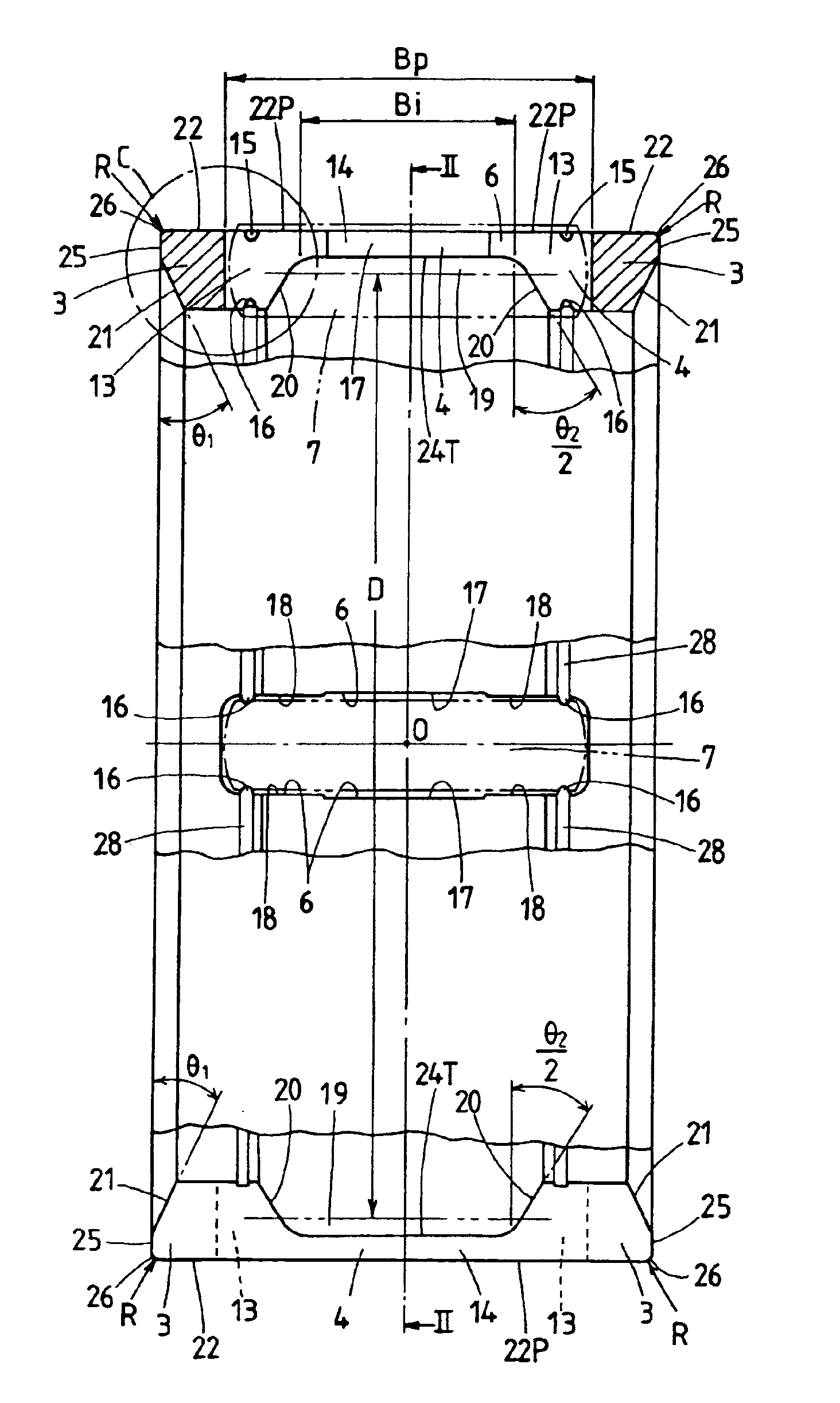
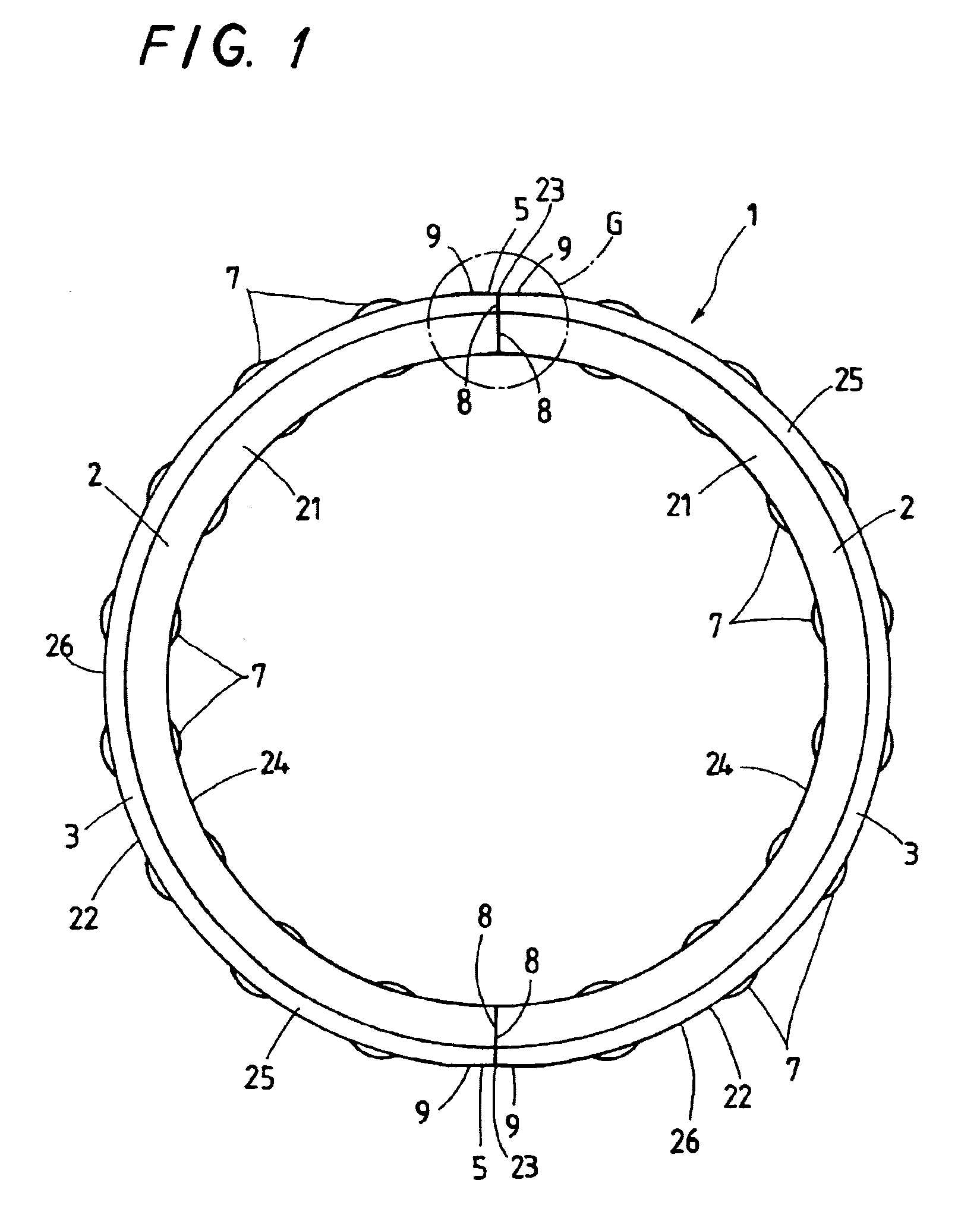
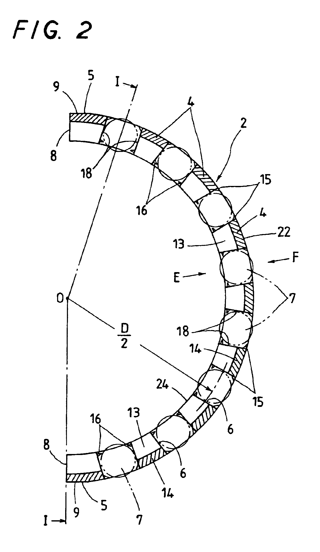
[0046]With the embodiment constructed as stated later, a roller bearing cage 1 is of the split type that mainly comprises a pair of semicircular cage halves 2 and has features of configuration, especially, at abutment ends 8 and areas nearby the ends. The roller bearing cage 1 is made of a cylindrical cage stock 10, which is split into two cage halves by cutting-off work to form a pair of semicircular cage halves 2. The cylindrical cage stock 10, as illustrated in FIGS. 6 and 7, is cut off at diametral opposing chamfered areas 9, in more detail, along a diametral plane 11 lying on circumferential midway points of the two diametral opposing cage bars 4 each of which is twice any other cage bar 4 in circumferential width. Each of the paired semicircular cage halves 2 fits into a bore in the rod end of the connecting rod in such a way...
PUM
 Abstract
Description
Claims
Application Information
 - R&D
- Intellectual Property
- Life Sciences
- Materials
- Tech Scout
- Unparalleled Data Quality
- Higher Quality Content
- 60% Fewer Hallucinations
Browse by: Latest US Patents, China's latest patents, Technical Efficacy Thesaurus, Application Domain, Technology Topic, Popular Technical Reports.
© 2025 PatSnap. All rights reserved.Legal|Privacy policy|Modern Slavery Act Transparency Statement|Sitemap|About US| Contact US: help@patsnap.com


