

Device and method for treating skin
- Summary
- Abstract
- Description
- Claims
- Application Information
AI Technical Summary
Benefits of technology
Problems solved by technology
Method used
Image

Examples
first embodiment
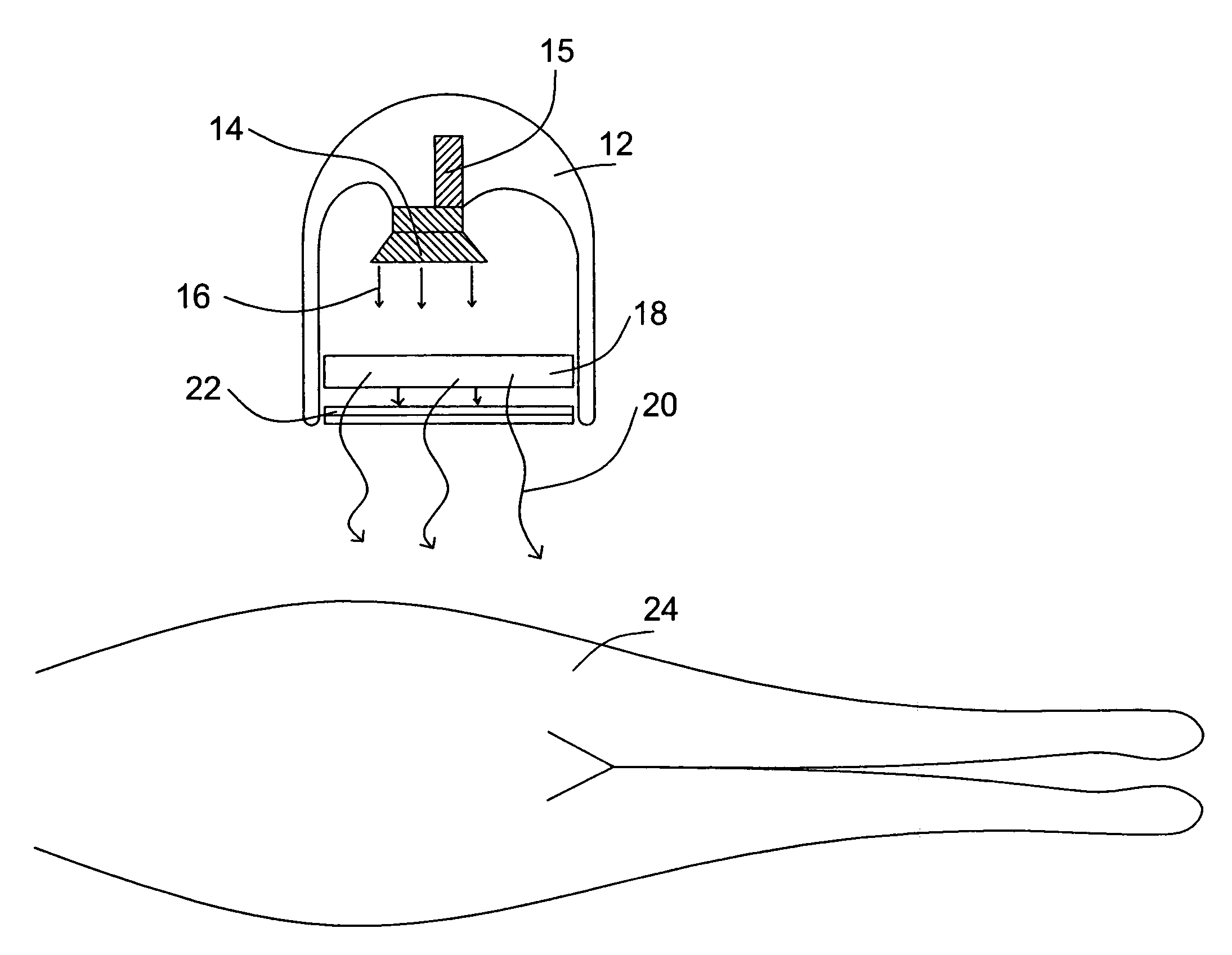
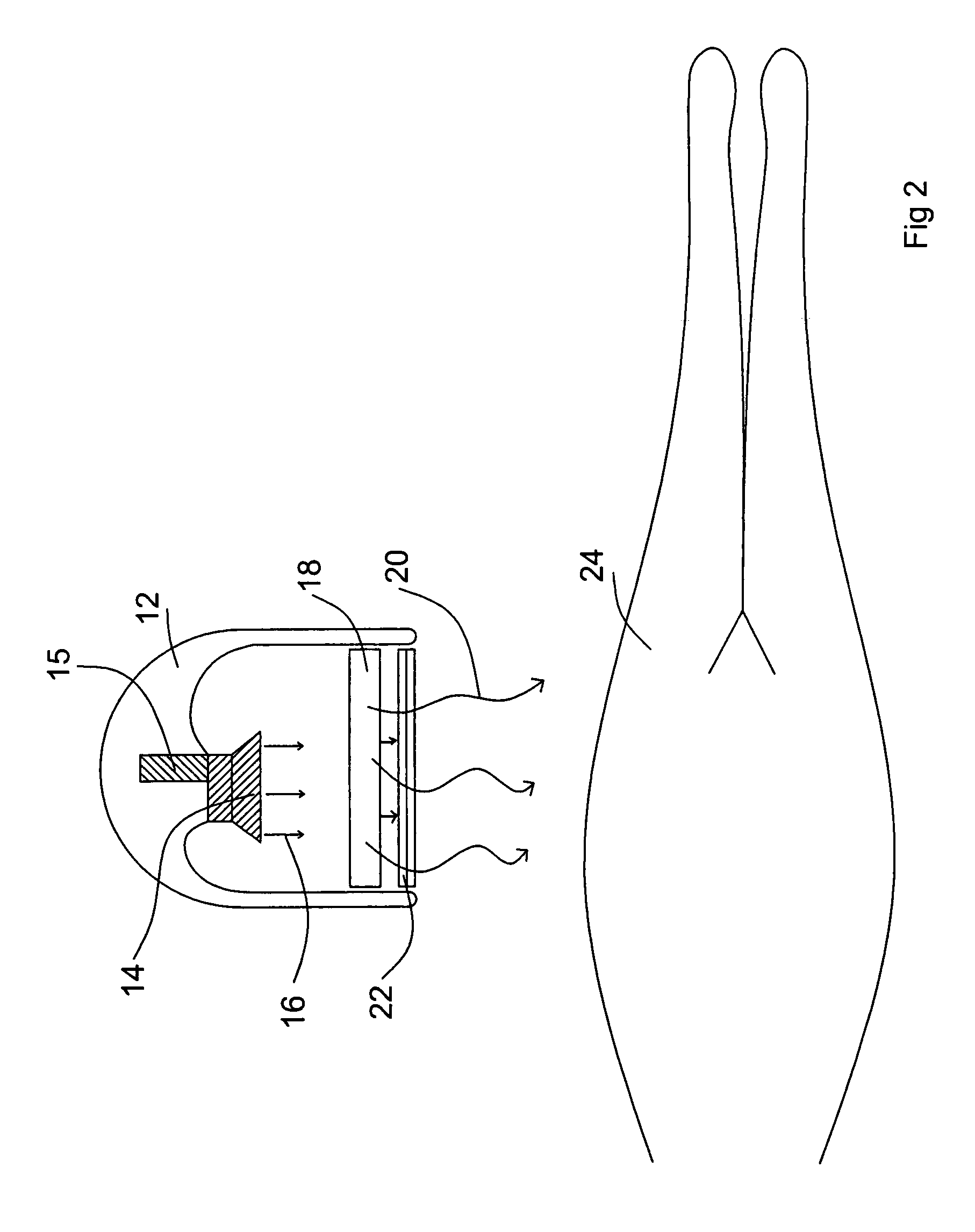
[0034]an illumination device of the present invention 10 is schematically depicted in FIG. 2. Inside a light proof housing 12 is found a water-cooled quartz-envelope high-pressure xenon flash lamp 14 fitted with a reflector. Further in illumination device 10 is found electrical pulse-forming network, 15 (such as manufactured by Perkin-Elmer Optoelectronics (Fremont, Calif., USA). Pulse forming network 15 allows flash lamp 14 to produce single or trains of flashes. A typical pulse-forming network can cause a xenon flash lamp, such as 14, to generate single or a train of light flashes with a total density of 1 to 200 j cm−2 and having a flash width of between 0.5 and 200 millseconds in duration.
[0035]When activated, flash lamp 14 repetitively produces intense flashes of light 16 over a wide range of wavelengths, with a large ultraviolet component. Ultraviolet pumped fluorescent block 18 absorbs ultraviolet light and re-emits light of a desired wavelength 20. Filter 22 prevents harmful...
second embodiment
[0036]an illumination device of the present invention 26 is schematically depicted in FIG. 3. Inside a light proof housing 28 is found a high-pressure xenon lamp 15. When activated, lamp 15 produces intense light 16 over a wide range of wavelengths, with a large ultraviolet component. Ultraviolet pumped fluorescent block 18 absorbs ultraviolet light and re-emits light of a desired wavelength 20. Baffles 30 which make up part of light proof housing 28 are positioned so that all light produced by lamp 15 and not confined to light proof housing 28 passes through ultraviolet pumped fluorescent block 18 in the direction of non-transparent block 32. Light produced by lamp 15 is therefore either used to pump fluorescent block 18 or harmlessly confined within device 26. In such a way skin 24 is illuminated only with light of desired wavelength 20 produced by ultraviolet pumped fluorescent block 18.
third embodiment
[0037]an illumination device 34 of the present invention is schematically depicted in FIG. 4. Inside casing 36 is found a laser 38 that efficiently produces ultraviolet light 40 (such as produced by Thermo Laser Science of Mountain View, Calif., USA). A first mirror 42 directs ultraviolet light 40 into a glass fiber light guide (Sumita Optical Glass, Inc. Saitama-Urawa, Japan) 44. Glass fiber light guide 44 directs ultraviolet light 40 to a second mirror 46. Second mirror 46 directs ultraviolet light 40 back through glass fiber light guide 44. In the path of ultraviolet light 38 is interposed ultraviolet pumped fluorescent block 18, held in place by fluorescent block holder 48. Ultraviolet light 40 produced by laser 38 is used to pump fluorescent block 18 or is harmlessly confined within casing 36 and glass fiber light guide 44. In such a way skin 24 is illuminated only with light of desired wavelength 20 produced by ultraviolet pumped fluorescent block 18. It is important to note t...
PUM
 Abstract
Description
Claims
Application Information