Thermal barrier coating

a technology of thermal barrier and coating, applied in the field of coatings, can solve the problems of significantly reducing the thermal conductivity of ysz, reducing erosion resistance, and characterized by inhomogeneity and porosity of tbc, and achieves enhanced erosion and impact resistance, low thermal conductivity, and low thermal conductivity.

Inactive Publication Date: 2006-01-03
GENERAL ELECTRIC CO
View PDF32 Cites 52 Cited by
  • Summary
  • Abstract
  • Description
  • Claims
  • Application Information

AI Technical Summary

Benefits of technology

[0011]As a result of the low thermal conductivity and relative thickness of the interior layer, the TBC preferably has a lower thermal conductivity than an equivalent columnar YSZ TBC while also exhibiting enhanced erosion and impact resistance as a result of the denser columnar construction of the outer surface region, which serves to protect the less erosion-resistant interior region. Accordingly, the TBC of this invention allows for the use of thinner coatings and / or lower cooling airflow for air-cooled components. Both regions of the TBC can be readily deposited by PVD techniques to have the more strain-resistant columnar grain structure noted above, with the closer column spacing of the outer surface region being achieved through compositional or processing modifications.

Problems solved by technology

Spraying techniques deposit TBC material in the form of molten splats, resulting in a TBC characterized by a degree of inhomogeneity and porosity.
According to Rigney et al., when present in sufficient amounts these oxides are able to significantly reduce the thermal conductivity of YSZ by increasing crystallographic defects and / or lattice strains.
The result of impingement can be erosive wear (generally from smaller particles) or impact spallation from larger particles.
Many of the oxides noted by Rigney et al. as able to reduce the thermal conductivity of YSZ have the disadvantage of also reducing erosion resistance.

Method used


Image

  • Thermal barrier coating
  • Thermal barrier coating
  • Thermal barrier coating

Examples


Embodiment Construction

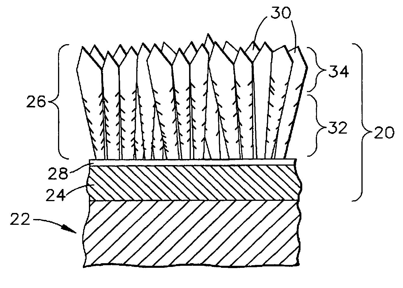
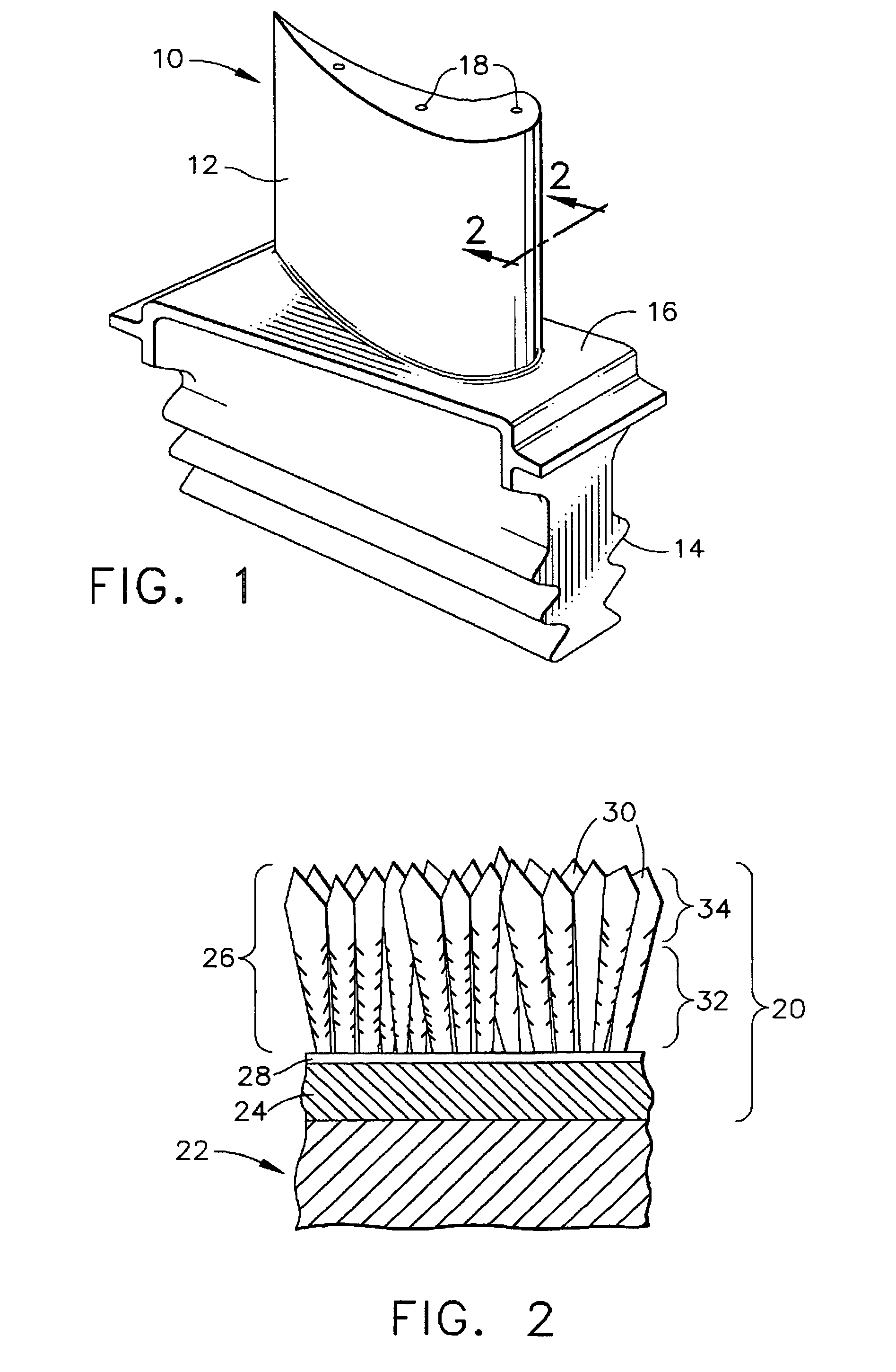
[0019]While the present invention is applicable to a variety of components subjected to high temperatures, such as the high and low pressure turbine nozzles and blades, shrouds, combustor liners and augmentor hardware of gas turbine engines, the invention will be discussed in reference to a high pressure turbine blade 10 shown in FIG. 1. The blade 10 generally includes an airfoil 12 against which hot combustion gases are directed during operation of the gas turbine engine, and whose surface is therefore subjected to hot combustion gases as well as attack by oxidation, corrosion and erosion. The airfoil 12 is protected from its hostile operating environment by a thermal barrier coating (TBC) system 20 schematically depicted in FIG. 2. The airfoil 12 is anchored to a turbine disk (not shown) with a dovetail 14 formed on a root section 16 of the blade 10. Cooling passages 18 are present in the airfoil 12 through which bleed air is forced to transfer heat from the blade 10.

[0020]The TBC...


PUM

PropertyMeasurementUnit
weight percentaaaaaaaaaa
thicknessaaaaaaaaaa
thicknessaaaaaaaaaa

Abstract

A thermal barrier coating (TBC) for a component intended for use in a hostile thermal environment. The TBC has an interior region and an outer surface region on and contacting the interior region. Both regions are formed of a ceramic material, with the interior region having a lower thermal conductivity than zirconia partially stabilized by about seven weight percent yttria. The interior region constitutes more than half of the thickness of the TBC, and the outer surface region constitutes less than half of the thickness of the TBC. The TBC has a columnar microstructure whereby the interior region and the outer surface region comprise columns of their ceramic materials. The outer surface region is more erosion and impact resistant than the interior region at least in part as a result of the columns thereof being more closely spaced than the columns of the interior region.

Description

FEDERAL RESEARCH STATEMENT[0001]This invention was made with Government support under Agreement No. N00421-00-3-0443 awarded by Naval Air Warfare Center Aircraft Division. The Government has certain rights in the invention.BACKGROUND OF INVENTION[0002]1. Field of the Invention[0003]This invention generally relates to coatings for components exposed to high temperatures, such as the hostile thermal environment of a gas turbine engine. More particularly, this invention is directed to a thermal barrier coating (TBC) having a columnar microstructure, an interior region formed of a ceramic material with lower thermal conductivity than yttria-stabilized zirconia (YSZ), and an outer surface region that is more erosion-resistant than the interior region of the TBC.[0004]2. Description of the Related Art[0005]Components within the hot gas path of gas turbine engines are often protected by a thermal barrier coating (TBC). TBC's are typically formed of ceramic materials deposited by plasma spr...

Claims


Application Information

Patent Timeline
Patent Type & Authority Patents(United States)
IPC IPC(8): B32B9/00F03B3/12C23C14/08C23C28/00F01D5/28
CPCC23C14/08C23C28/321C23C28/3215C23C28/345C23C28/3455F01D5/288C23C14/083Y10T428/24413Y02T50/67Y02T50/671F05D2230/90F05D2300/611Y10T428/24355Y10T428/12611Y10T428/12618Y02T50/60
Inventor DAROLIA, RAMGOPALSPITSBERG, IRENEBOUTWELL, BRETT ALLEN ROHRERGORMAN, MARK DANIELJOHNSON, CURTIS ALANVENKATARAMANI, VENKAT SUBRAMANIAM
Owner GENERAL ELECTRIC CO
Why Eureka
Try Eureka