Battery management system and method

a battery system and management system technology, applied in the direction of multiple simultaneous battery arrangement, amplifier modification to reduce noise influence, thermometer testing/calibration, etc., can solve the problems of over-charged cells, poor recharging characteristics, permanent damage, etc., to prolong the battery life, confirm the electrochemical stability of the battery string, and confirm the temperature stability of each unit.

Inactive Publication Date: 2006-01-03
SCHNEIDER ELECTRIC IT CORP
View PDF84 Cites 204 Cited by
  • Summary
  • Abstract
  • Description
  • Claims
  • Application Information

AI Technical Summary

Benefits of technology

[0035]capable of confirming the electrochemical stability of the battery string; and capable of confirming the temperature stability of each unit.
[0036]Generally, the present invention relates to the management of stationary batteries in standby applications for the purpose of monitoring and alarming critical battery parameters, extending battery life and improving the reliability of critical power loads.
[0037]According to another aspect of the invention, the battery management system is controlled by a microprocessor and may be interfaced with a remote personal computer. The system is capable of selectively coupling to any one of the individual units of the battery to measure its characteristics, including voltage, discharge current, temperature and electrochemical status by providing electrically isolated charging current from the system isolated power supply to any individual unit of the battery for the purpose of confirming the electrochemical stability and maintaining an equal individual unit state of charge. The coupling is safe, electrically isolated and positive.

Problems solved by technology

An overly discharged cell develops poor recharging characteristics and can be permanently damaged.
A damaged cell will affect the operating characteristics of the entire battery.
The damaged battery will have lower capacity and will become discharged more rapidly than a healthy battery.
The failure of an individual cell can cause substantial damage to the battery system and accompanying equipment.
For example, recently the failure of one cell of a battery string caused an entire turbine generator to be destroyed.
However, balancing is a slow process.
Also, continuous charging of the battery may cause some cells to be overcharged, which further damages the cells.
However, such systems have generally not automatically managed batteries effectively, or in a cost-conscious manner.
Furthermore, such systems have not utilized the processing power of computers in connection with battery management.
The lack of consistent individual treatment leads to premature deterioration, individual cell failures and failure of the entire battery string or bank, which in turn can lead to costly problems or downtime in the system that the battery serves.
The device of the aforementioned patent does not have the capability of singling out individual cells and then charging those cells.
Generally, the device of the aforementioned patent would tend to have noise problems in an industrial environment.
Additionally, the device of the aforementioned patent does not appear to have the ability to store test data, nor does it have the ability to analyze the voltage of the individual cells or perform capacity tests.
Nevertheless, other than measuring the voltage of the cells and charging them when they are not fully charged, the system does not offer a comprehensive ability to manage a battery system.

Method used


Image

  • Battery management system and method
  • Battery management system and method
  • Battery management system and method

Examples


Embodiment Construction

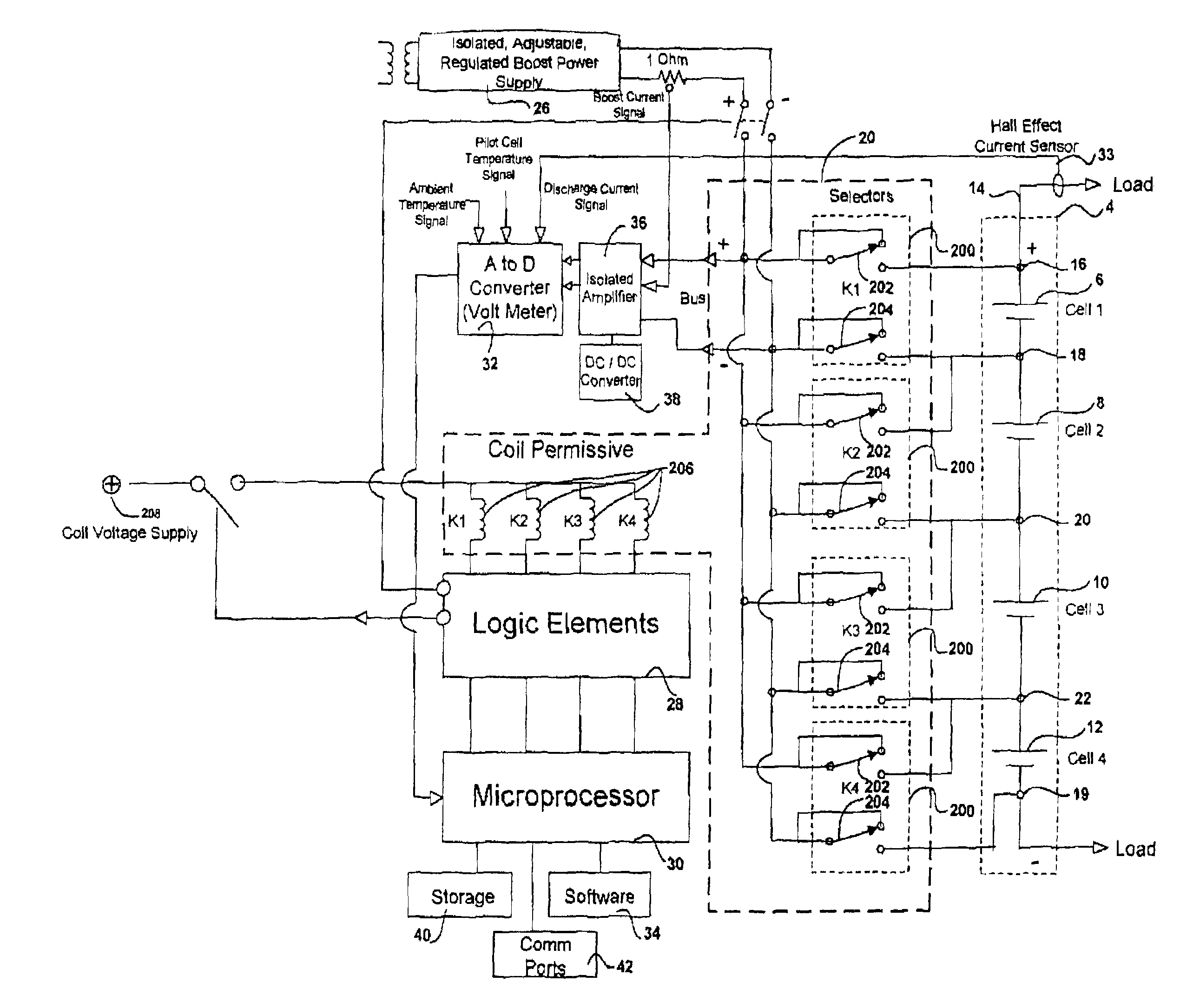
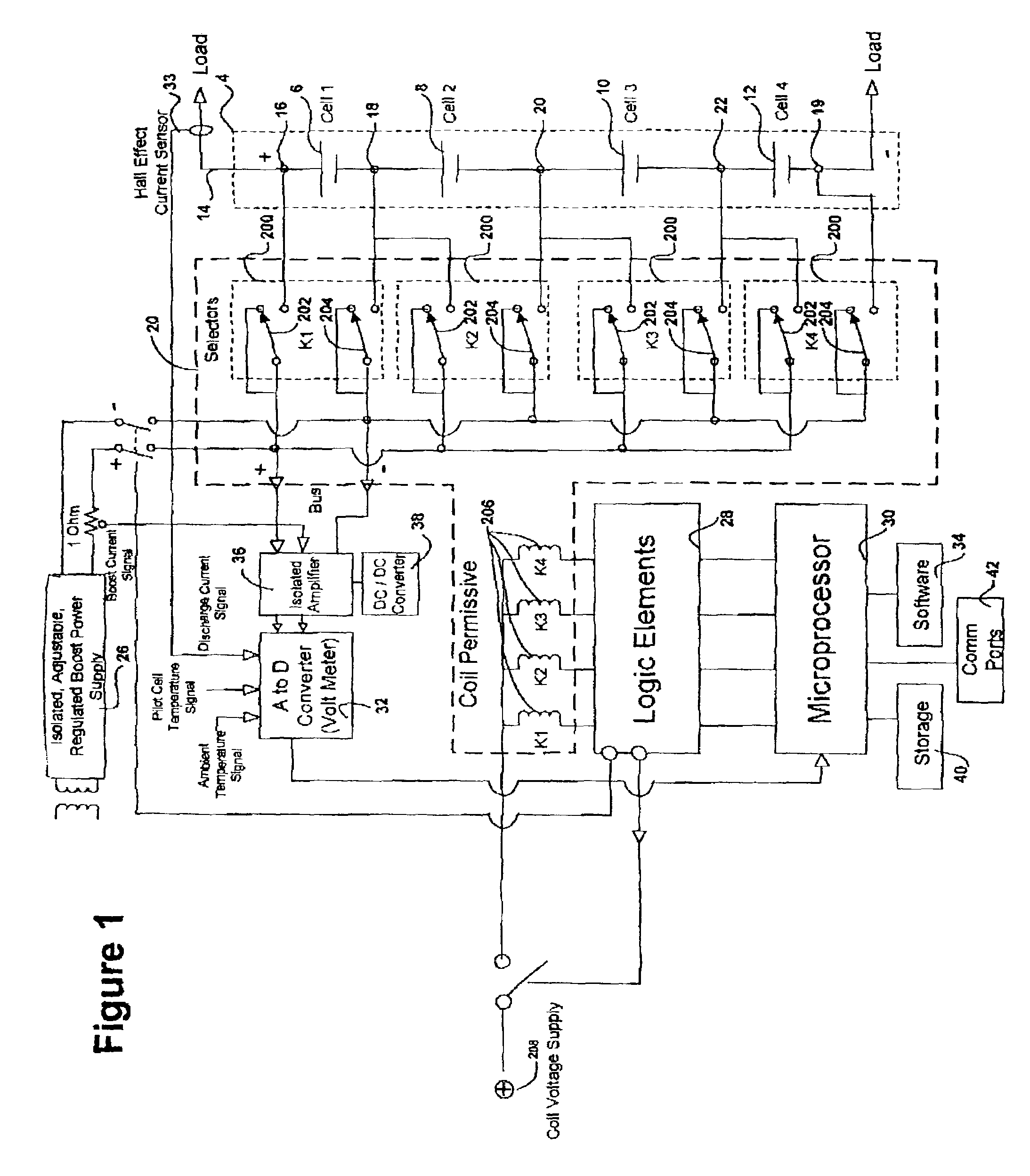
[0041]The overall purpose of the system is to automatically manage each individual battery unit, one of a plurality of cells in a battery string under dynamic and static conditions. The identity of multiple individual units exhibiting a problem is visually prompted along with a detailed time dated report on the system disk and / or printer.

[0042]FIG. 1 illustrates the overall apparatus for managing a battery according to the present invention. The system is used in conjunction with an “external” or “main” charger that is used for bulk charging of the battery and is not shown. Likewise, the load is not shown. As shown therein, a battery string 4 has a plurality of cells 6, 8, 10,12 (only four are shown, for illustrative clarity) connected electrically in series with one another by cell connectors or terminals 18 (between cells 6 and 8), 20 (between cells 8 and 10) and 22 (between cells 10 and 12). A first one of the series of cells has a terminal 16 , and a last one of the series of ce...


PUM


Abstract

A battery management system is disclosed for control of individual cells in a battery string. The battery management system includes a charger, a voltmeter, a selection circuit and a microprocessor. Under control of the microprocessor, the selection circuit connects each cell of the battery string to the charger and voltmeter. Information relating to battery performance is recorded and analyzed. The analysis depends upon the conditions under which the battery is operating. By monitoring the battery performance under different conditions, problems with individual cells can be determined and corrected.

Description

[0001]This application claims the benefit of Provisional Application No. 60 / 333,536, filed Nov. 27, 2001.BACKGROUND OF THE INVENTION[0002]1. Field of the Invention[0003]The invention relates to a method and apparatus for management of individual cells in a battery system, particularly electrochemical, rechargeable cells.[0004]2. Discussion of Related Art[0005]Typically, battery systems, such as battery banks or strings, include a plurality of individual cells. A “cell” can mean a single electrochemical cell comprised of the most basic units, i.e. a positive plate, a negative plate, and an electrolyte. However, as used herein, the term is not so limited and includes a group of basic cells that can comprise single unit as a component of a battery string. A battery or battery string is a series connection of units or individual cells.[0006]There is a tendency for each cell within individual batteries, when connected in series, to have a different characteristics, such as energy storage...

Claims


Application Information

Patent Timeline
Patent Type & Authority Patents(United States)
IPC IPC(8): G06F19/00H02J7/00
CPCH02J7/0021H02J7/0019H02J7/0014H02J7/0048H02J7/005
Inventor BURNS, CHARLES E.
Owner SCHNEIDER ELECTRIC IT CORP
Why Eureka
Try Eureka