Chemical reactor for gas phase reactant catalytic reactions

a catalyst reaction and chemical reactor technology, applied in catalyst activation/preparation, metal/metal-oxide/metal-hydroxide catalysts, bulk chemical production, etc., can solve the problems of aluminum application, large equipment volume, and large usable surface area of microchannel walls, so as to reduce pressure drop

Inactive Publication Date: 2006-01-10
BATTELLE MEMORIAL INST
View PDF39 Cites 44 Cited by
  • Summary
  • Abstract
  • Description
  • Claims
  • Application Information

AI Technical Summary

Benefits of technology

[0022]A significant advantage of the present invention is the reduced pressure drop because the flow through the bulk flow path passes and contacts the porous structure but is not required to flow through the porous structure. Sufficient reaction still occurs because of the net flux through molecular diffusion into (gas phase reactant(s)) and out of (product(s)) the porous structure. Gas hourly space velocity is unexpectedly greater than 10,000 hr−1 correspond...

Problems solved by technology

However, equipment, specifically reactor volume is generally large because of mass and heat transfer limitations.
This approach has the disadvantage that the only usable surface area is that of the microchannel wall.
Disadvantages of this approach include th...

Method used


Image

  • Chemical reactor for gas phase reactant catalytic reactions
  • Chemical reactor for gas phase reactant catalytic reactions
  • Chemical reactor for gas phase reactant catalytic reactions

Examples


example 1

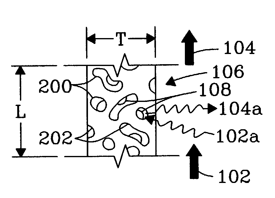
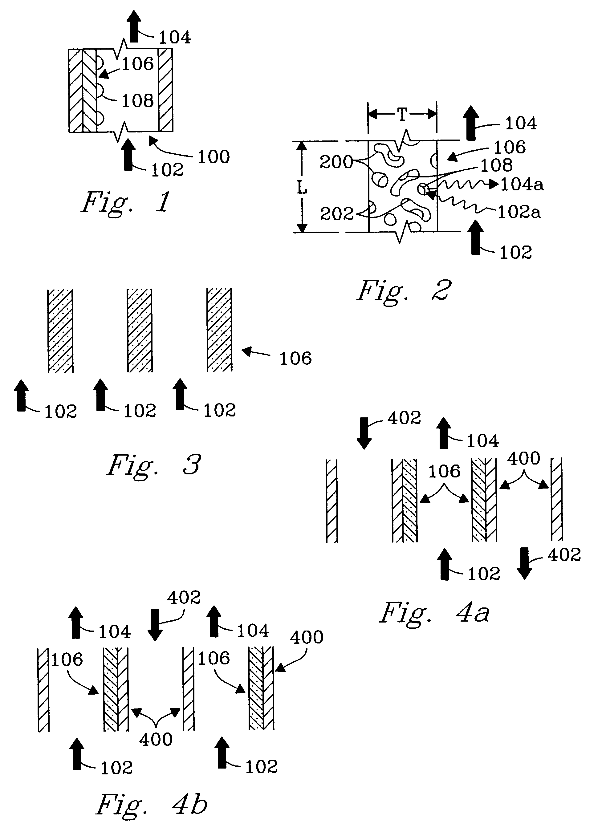
[0044]An experiment was conducted to demonstrate the present invention using 1 microchannel for methane steam reforming. The microchannel was placed within a tube furnace to provide the required endothermic reaction heat. The microchannel was 1.52-cm long and 0.66-cm high. The width (or opening) of the microchannel was 0.0762-cm or 762-microns. The 0.0762-cm width included two porous structures that covered opposite walls and each had a width of 254-microns leaving a bulk flow path between the two porous structures of 254 microns. The porous structure contained a catalyst of 13.8%-Rh / 6%-MgO / Al2O3 on a metal felt of stainless steel obtained from Technetics, Deland, Fla.

[0045]The methane inlet flowrate was 50.3-cc / min at standard conditions and the water (liquid) flowrate was 7.3 mL / hr, corresponding to a steam to carbon ratio of approximately 3:1. The methane and water were preheated to near the reaction temperature before entering the microchannel. Gas flow was in the bulk flow path...

example 2

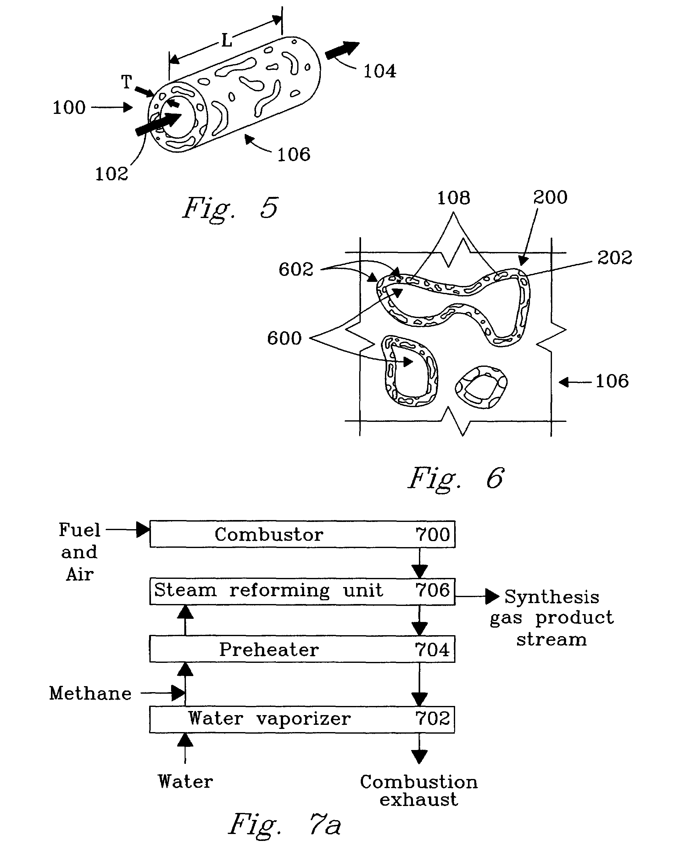
[0048]An experiment was conducted to demonstrate the present invention. The apparatus (FIG. 7a) included a fuel combustor 700, water vaporizer 702, a reactant preheat heat exchanger 704, and a steam-reforming unit 706. The steam reforming unit 706 was constructed with 12 parallel channels (FIG. 7b) 1, 2, 3 . . . 12 each of length 2.79 cm, height 2.54 cm, and width of 750 microns. The porous structure 106 was felt metal of stainless steel with a porosity ranging from 35% to 90% obtained from Technetics, Orlando, Fla., having a width of about 250 micron. Pieces of metal felt with length and height nearly equal to the channel length and height were affixed to the walls on opposite sides of the channels leaving a bulk flow path of about 250 microns in each channel. The reactor microchannels were interspersed with heat exchange channels a, b, c . . . m to provide the endothermic reaction heat. The adjacent (and interleaved) parallel heat exchange microchannels (13 total) were hermeticall...


PUM

PropertyMeasurementUnit
Lengthaaaaaaaaaa
Fractionaaaaaaaaaa
Pore sizeaaaaaaaaaa

Abstract

The present invention is a chemical reactor for catalytic chemical reactions having gas phase reactants. The chemical reactor has reactor microchannels for flow of at least one reactant and at least one product, and a catalyst material wherein the at least one reactant contacts the catalyst material and reacts to form the at least one product. The improvement, according to the present invention is: the catalyst material is on a porous material having a porosity that resists bulk flow therethrough and permits molecular diffusion therein. The porous material further has a length, a width and a thickness, the porous material defining at least a portion of one wall of a bulk flow path through which the at least one reactant passes.

Description

[0001]This application is a divisional of U.S. application Ser. No. 09 / 375,614, filed Aug. 17, 1999 now U.S. Pat. No. 6,488,838.FIELD OF THE INVENTION[0002]The present invention is a chemical reactor and method for gas phase reactant catalytic reactions.[0003]As used herein, the term “molecular diffusion” is used in its classic sense of the transfer of mass based upon Brownian motion between adjacent layers of fluid in laminar, transition, or turbulent flow, and includes transfer of mass between adjacent layers of fluid that are stagnant.[0004]As used herein, the term “Knudsen diffusion” means Knudsen flow, or free molecule flow, wherein the mean free path of the molecules is long compared to a characteristic dimension of the flow field, for example the pore size of a material through which the molecules are diffusing.BACKGROUND OF THE INVENTION[0005]Many catalytic reactions begin with gas phase reactants, for example steam reforming, partial oxidation, water gas shift and others. H...

Claims


Application Information

Patent Timeline
IPC IPC(8): B01J35/00B01J8/02B01D53/22B01D71/02B01J12/00B01J19/00B01J19/24B01J23/60B01J37/02B01J37/03C01B3/38C01B3/48C01B3/50C01B3/56C01B13/02H01M8/06
CPCB01J12/007B01J23/60B01J37/0215C01B3/38C01B3/384C01B3/501C01B13/0251H01M8/0612B01J19/0093Y02E60/50B01J23/58B01J35/04B01J37/031B01J2219/00159B01J2219/00783B01J2219/00822B01J2219/00824B01J2219/00835B01J2219/00844B01J2219/00873B01J2219/00907B01J2219/00984B01J2219/2453B01J2219/2465B01J2219/2474B01J2219/2475B01J2219/2479B01J2219/2482B01J2219/2497C01B2203/0233C01B2203/0283C01B2203/0405C01B2203/041C01B2203/044C01B2203/047C01B2203/065C01B2203/066C01B2203/0811C01B2203/0822C01B2203/0833C01B2203/0838C01B2203/1005C01B2203/1011C01B2203/1029C01B2203/1035C01B2203/1041C01B2203/1047C01B2203/1052C01B2203/1064C01B2203/1076C01B2203/1082C01B2203/1094C01B2203/1217C01B2203/1223C01B2203/1241C01B2203/1258C01B2203/1276C01B2203/1288C01B2203/148C01B2203/1604C01B2203/1619C01B2203/1652C01B2203/1676C01B2210/0046Y02P20/52Y02P20/10
Inventor TONKOVICH, ANNA LEE Y.WANG, YONGFITZGERALD, SEAN P.MARCO, JENNIFER L.ROBERTS, GARY L.VANDERWIEL, DAVID P.WEGENG, ROBERT S.
Owner BATTELLE MEMORIAL INST
Why Eureka
Try Eureka