Projection system for EUV lithography

a projection system and lithography technology, applied in the field of microlithography objectives, can solve the problems of reducing the throughput of the entire projection apparatus, the system is very long (3000 mm), and the examples are not well suited to contemporary lithography at extreme ultraviolet wavelengths, etc., to achieve the effect of efficient masking of undesired light, easy manufacturing, and convenient mechanical achievemen

Inactive Publication Date: 2006-01-10
CARL ZEISS SMT GMBH
View PDF33 Cites 35 Cited by
  • Summary
  • Abstract
  • Description
  • Claims
  • Application Information

AI Technical Summary

Benefits of technology

[0033]The objective can be used not only in the EUV, but also at other wavelengths, without deviating from the scope of the invention. In any respect, however, to avoid degradation of image quality, especially degradation due to central shading, the mirrors of the projection objectives should be arranged so that the light path of the bundle of light rays traveling from the object plane to the image plane is obscuration-free. Furthermore, to provide easy mounting and adjusting of the system, the physical mirror surfaces have a rotational symmetry to a principal axis (PA). Moreover, to have a compact design with an accessible aperture and to establish an obscuration-free light path of the bundle of light rays traveling from the object plane to the image plane, the projection objective device is designed in such a way that an intermediate image of the object situated in the object plane is formed after the fourth mirror. In such systems, it is possible that the aperture stop is situated in the front, low-aperture objective part, with a pupil plane conjugated to the aperture stop imaged in the focal plane of the last mirror. Such a system ensures telecentricity in the image plane.
[0035]Furthermore, in order to prevent vignetting of the light running from the third to the fourth mirror, by the aperture stop arranged between the second and third mirror, the ratio of the distance between the second mirror and aperture stop to the distance between the third mirror and the aperture stop lies in the range:0.5<S2 aperture / (S3 aperture)<2.In such a system, the angles of incidence on the physical mirror surfaces in the front part of the objective are reduced.
[0036]An aperture stop which physically lies between the second mirror, S2, and the first mirror, S1, must be formed at least partially as a narrow ring in order to avoid clipping of light moving from S1 to S2. In such a design, there is a danger that undesirable direct light or light reflected on S1 and S2, will pass outside the aperture ring and reach the image plane and thus the wafer. However, if the aperture stop is placed in the light path between the second and third mirror and physically close to the first mirror (which can be easily achieved mechanically), an efficient masking of this undesired light is possible. The aperture stop can be designed both as an opening in the first mirror or an opening which is arranged behind the first mirror.
[0037]In another embodiment of the invention, the aperture stop is arranged on or near the second mirror. Arrangement of the aperture on a mirror has the advantage that it is easier to manufacture.
[0039]In order to be able to make the necessary corrections of imaging errors in the six-mirror systems, in a preferred embodiment, all six mirrors are designed to be aspherical. However, an alternative embodiment whereby at most five mirrors are aspherical can simplify the manufacturing, because it is then possible to design one mirror, preferably the largest mirror, i.e., the quaternary mirror, in the form of a spherical mirror. Moreover, it is preferred that the second to sixth mirror be in a concave-convex-concave-convex-concave sequence.

Problems solved by technology

This reduction in ring field width results directly in reduced throughput of the entire projection apparatus.
While minimizing the number of reflections has several advantages particular to EUV lithography, an odd number of reflections create a problem in that new stage technology would need to be developed to enable unlimited parallel scanning.
While the embodiments disclosed in the '240 patent appear to achieve their stated purpose, these examples are not well suited for contemporary lithography at extreme ultraviolet wavelengths.
First, the systems are very long (˜3000 mm) and would suffer mechanical stability problems.
Second, the embodiments do not support telecentric imaging at the image which is desired for modern semiconductor lithography printing systems.
Lastly, the numerical aperture is rather small (˜0.05) leaving the systems unable to address 30 nm design rules.
While these systems were designed for DUV lithography and are fine for that purpose, these embodiments make very poor EUV projection systems.
Even after the numerical aperture is reduced from 0.50 to 0.25, the incidence angles of the ray bundles are very large at every mirror including the mask, making the system incompatible with either Mo / Si or Mo / Be multilayers.
While the prior art projection optical systems have proven adequate for many applications, they're not without design compromises that may not provide an optimum solution in all applications.

Method used


Image

  • Projection system for EUV lithography
  • Projection system for EUV lithography
  • Projection system for EUV lithography

Examples


first embodiment

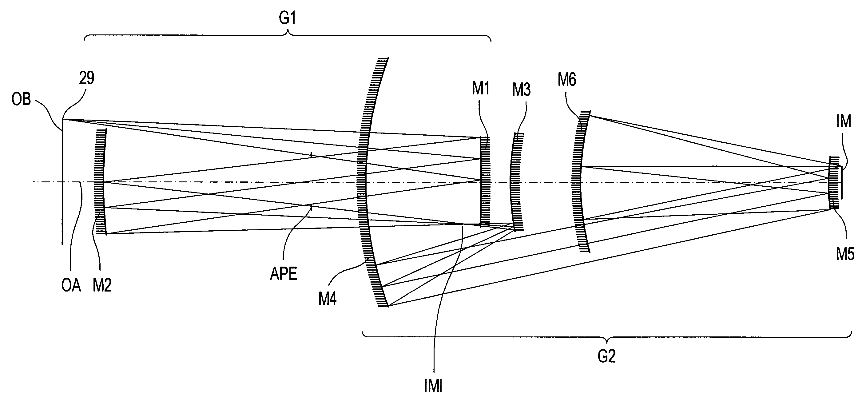
[0072]The optical prescription of FIG. 1 is listed in Table 1 and Table 2. The aspheric mirror surfaces are labeled A(1)–A(6) in the tables with A(1) corresponding to mirror M1, A(2) corresponding to mirror M2, and so on. Four additional surfaces complete the description of this illustrative and exemplary embodiment with object OB and image IM representing the planes, where in a lithographic apparatus the mask and the wafer are arranged. A surface designation is also made for the location of the aperture stop APE and intermediate image IMI. After each surface designation, there are two additional entries listing the vertex radius of curvature (R) and the vertex spacing between the optical surfaces. In this particular embodiment, each of the surfaces is rotationally symmetric conic surface with higher-order polynomial deformations. The aspheric profile is uniquely determined by its K, A, B, C, D, and E values. Each mirror uses 4th, 6th, 8th, 10th, and 12th order polynomial deformatio...

second embodiment

[0080]In addition to the features outlined by the first preferred embodiment, this second preferred embodiment teaches that the tertiary mirror M3′ may be located on the object side of the primary mirror M1′ (i.e., closer to the object OB′ than the primary mirror M1′). This feature departs drastically from the teaches of the prior art that show the tertiary mirror must be located either in close proximity to the primary mirror('079 patent) or on the image side of the primary mirror('310 patent). This location of mirror M3′ enables a reduction in the overall length from object plane OB to image plane IM (total track length) by some 250 mm. This decrease in total track length is accomplished by shifting the tertiary mirror from the image side of the primary mirror M1′ to the object side of the primary mirror M1′ and then decreasing the distance between mirror M1′ and mirror M6′. This also allows the parent diameter of the tertiary mirror M3′ to be smaller than either the primary mirro...

third embodiment

[0087]The optical prescription for this third embodiment of FIG. 4 is listed in Table 7 and Table 7. Table 7 lists the vertex radius of curvature as well as the separation between these mirrors along the optical axis. Each mirror is aspheric and labeled A(1)–A(6) in the tables with A(1) corresponding to mirror M1″, A(2) corresponding to mirror M2″, and so on. The prescription of the aspheric surface deformation per equation (1) is listed in Table 8. Taken together with the information provided in Table 9, an illustrative and exempary description of this prefered embodiment is disclosed.

[0088]Like the first two preferred embodiments, the object OB″, e.g. a pattern on mask or reticle, will be projected to the image IM″ at 4× reduction in a ring field format with a telecentric imaging bundle (chief rays parallel to the optical axis at the image). At the image″ typically a semiconductor wafer is arranged. Table 6 provides a performance summary demonstrating that this preferred embodimen...


PUM

PropertyMeasurementUnit
physical distanceaaaaaaaaaa
incidence angleaaaaaaaaaa

Abstract

An EUV optical projection system includes at least six reflecting surfaces for imaging an object (OB) on an image (IM). The system is preferably configured to form an intermediate image (IMI) along an optical path from the object (OB) to the image (IM) between a secondary mirror (M2) and a tertiary mirror (M3), such that a primary mirror (M1) and the secondary mirror (M2) form a first optical group (G1) and the tertiary mirror (M3), a fourth mirror (M4), a fifth mirror (M5) and a sixth mirror (M6) form a second optical group (G2). The system also preferably includes an aperture stop (APE) located along the optical path from the object (OB) to the image (IM) between the primary mirror (M1) and the secondary mirror (M2). The secondary mirror (M2) is preferably concave, and the tertiary mirror (M3) is preferably convex. Each of the six reflecting surfaces preferably receives a chief ray (CR) from a central field point at an incidence angle of less than substantially 15°. The system preferably has a numerical aperture greater than 0.18 at the image (IM). The system is preferably configured such that a chief ray (CR) converges toward the optical axis (OA) while propagating between the secondary mirror (M2) and the tertiary mirror (M3).

Description

CROSS-REFERENCE TO RELATED APPLICATIONS[0001]The present application is a continuation of International Application No. PCT / EP01 / 14301 and a continuation-in-part of U.S. patent application Ser. No. 10 / 004,674. The PCT / EP01 / 14301 application was filed Dec. 6, 2001, and claims priority of U.S. Provisional Patent Application Ser. No. 60 / 255,161, which was filed Dec. 12, 2000. The Ser. No. 10 / 004,674 application was filed Dec. 3, 2001 now U.S. Pat. No. 6,600,552 and is a continuation-in-part of U.S. patent application Ser. No. 09 / 503,640. The Ser. No. 09 / 503,640 application was filed Feb. 14, 2000 and issued as U.S. Pat. No. 6,353,470. The present application is also claiming priority of (a) German Patent Application No. 199 06 001 filed Feb. 15, 1999, and (b) German Patent Application No. 199 48 240 filed Oct. 7, 1999.BACKGROUND OF THE INVENTION[0002]1. Field of the Invention[0003]The present invention relates to a microlithography objective, a projection exposure apparatus containing ...

Claims


Application Information

Patent Timeline
Patent Type & Authority Patents(United States)
IPC IPC(8): G03B27/54G03B27/42G02B11/00G02B13/24G02B17/06G03F7/20H01L21/027
CPCG02B17/0652G02B17/0657G03F7/70275G03F7/70233G03B27/54
Inventor HUDYMA, RUSSELLMANN, HANS-JURGENDINGER, UDO
Owner CARL ZEISS SMT GMBH
Why Eureka
Try Eureka