
Fuel flexible thermoelectric micro-generator with micro-turbine

a micro-generator and thermoelectric technology, applied in generators/motors, machines/engines, lighting and heating apparatus, etc., can solve the problems of limiting the types of portable electronic devices and mems with which it can be used, and limiting the amount of power which can be obtained from the device. , to achieve the effect of enhancing overall system efficiency and total electrical energy outpu

Active Publication Date: 2006-01-17
HARRIS CORP
View PDF17 Cites 25 Cited by
  • Summary
  • Abstract
  • Description
  • Claims
  • Application Information

AI Technical Summary

Benefits of technology

[0008]Another important aspect of this invention is that the micro-combustor can be operated with a variety of different hydrocarbon fuels including both those which are in vapor form at ambient temperatures, such as propane and butane, and those in liquid form, e.g., gasoline, kerosene, diesel fuel and the like. This capability allows the micro-generator of this invention to be used in virtually any location where there is a source of hydrocarbon fuel.
[0009]Overall system efficiency and total electrical energy output is enhanced by connecting a micro-turbine to the exhaust outlet of the micro-combustor. This provides a second source of electrical energy, in addition to that produced by the thermoelectric module.

Problems solved by technology

Notwithstanding these improvements, batteries are fundamentally limited in terms of power generation per unit volume, energy storage per unit mass and disposal of the ultimate by-products of power generation, e.g. toxic metals.
Even at comparatively low rates of efficiency in converting thermal energy resulting from the combustion of hydrocarbon fuels to electrical energy, the energy storage density is much higher using hydrocarbon fuels in comparison to batteries.
This limits the amount of power which can be obtained from the device, and therefore restricts the types of portable electronic devices and MEMS with which it can be used.
Additionally, fuel consumption can become an issue given such a low conversion efficiency.
Consequently, the micro-generator of the '972 patent has limited practical application in its present form.

Method used


Image

  • Fuel flexible thermoelectric micro-generator with micro-turbine
  • Fuel flexible thermoelectric micro-generator with micro-turbine
  • Fuel flexible thermoelectric micro-generator with micro-turbine

Examples


Embodiment Construction

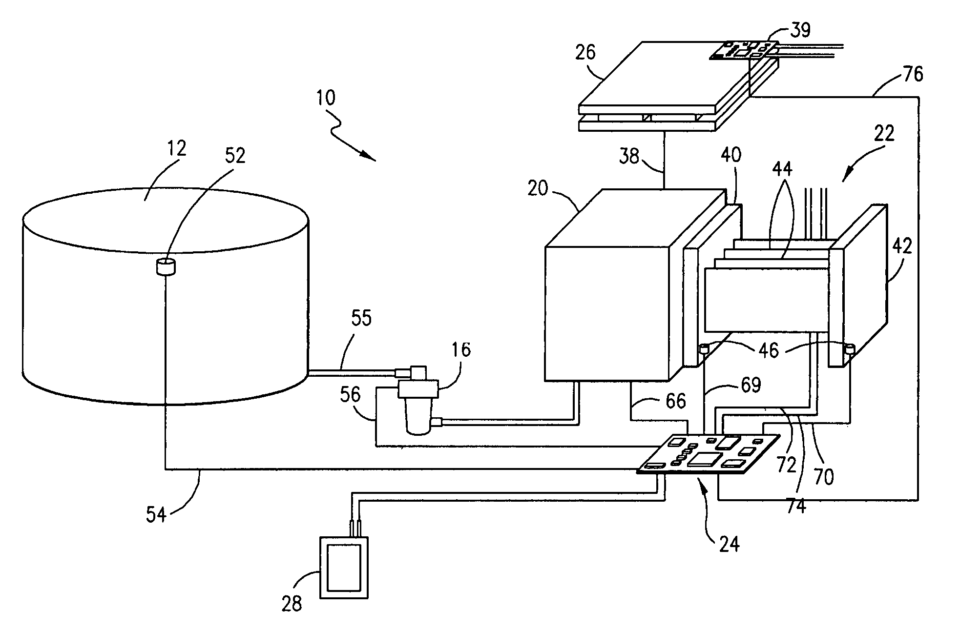
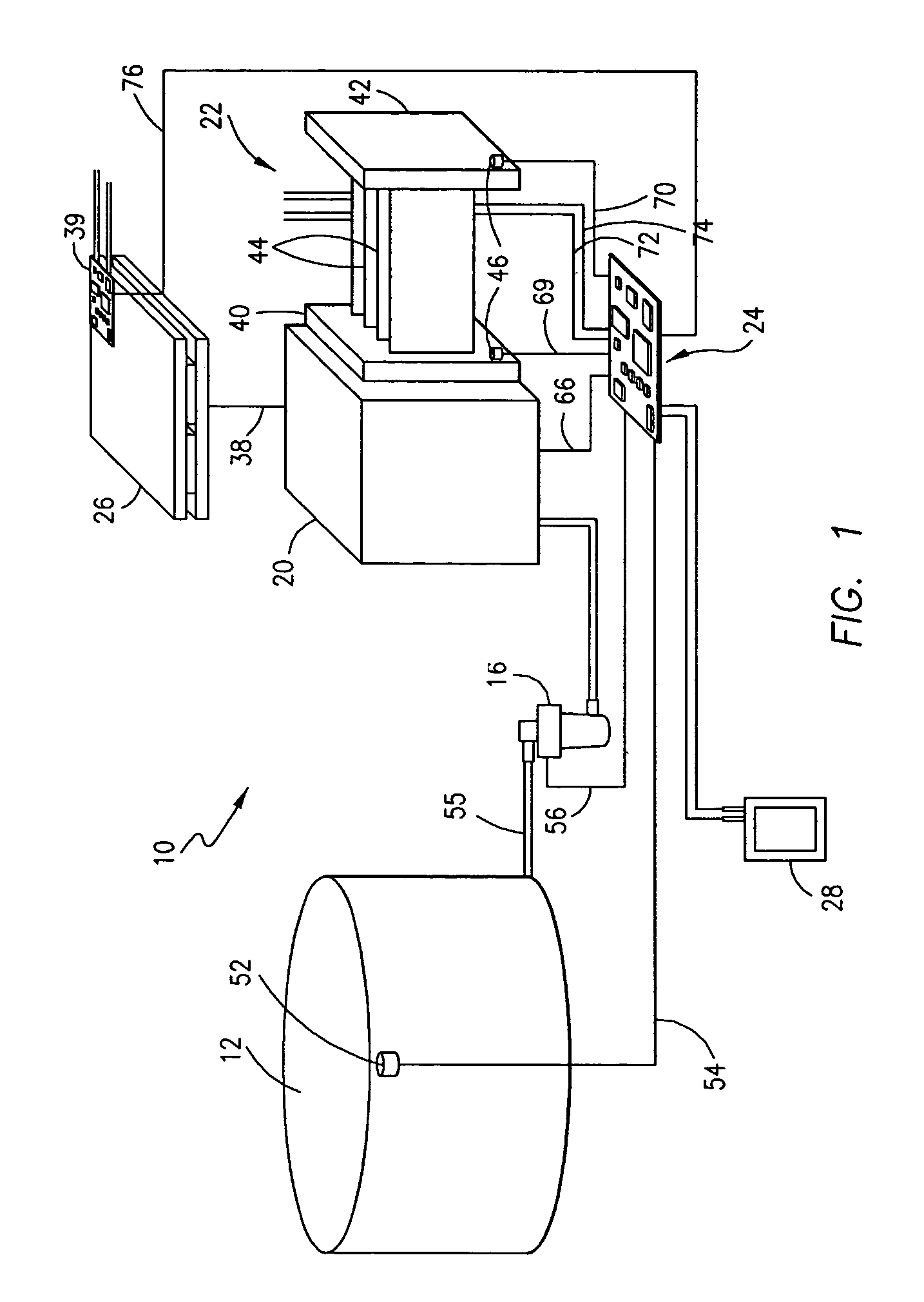
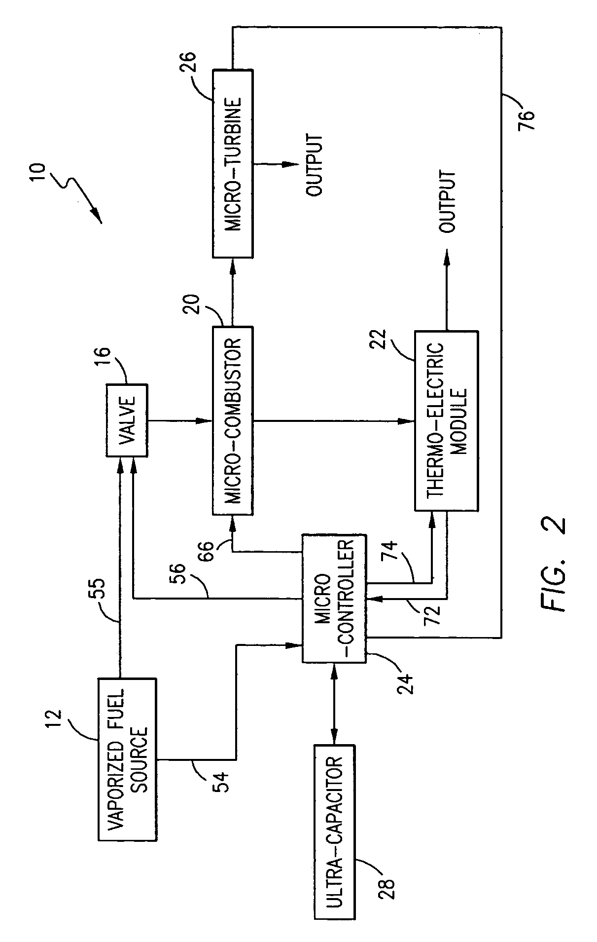
[0017]Referring now to the FIGS. 1, 2 and 5, one embodiment of a micro-generator system 10 is schematically depicted in FIG. 1. The system 10 includes a fuel source 12, a fuel control valve 16, a micro-combustor 20, a thermoelectric module 22, a micro-controller 24 with an LCD or other display (not shown), a micro-turbine 26, and, an ultra-capacitor 28. The thermoelectric module 22 of the system 10 is operative to generate approximately 168 milliamps at 12 volts DC using the configuration described below, and additional electrical energy is output from the micro-turbine 26. It should be understood, however, that the system 10 is scalable and its components can be altered in size and capacity to increase the power output, as desired. The several elements of the system 10, as well as an alternative system 50, are described below followed by a discussion of their overall operation.

[0018]The heart of the system 10 is the micro-combustor 20 which is a modified version of the micro-combus...


PUM


Abstract

A micro-generator for providing electrical energy to portable electronic devices and MEMS includes a micro-combustor, a micro-turbine connected to the exhaust outlet of the micro-combustor and a thermoelectric module consisting of a number of quantum well thermoelectric panels connected between spaced heat spreaders, one of which is mounted in thermal communication with the micro-combustor. Different types of hydrocarbon fuel may be supplied to the micro-combustor where it is burned within a combustion chamber. The entire system is controlled in real time by a micro-controller which is powered upon start up by an ultra capacitor and thereafter by the electric energy produced by the thermoelectric module and / or the micro-turbine.

Description

FIELD OF THE INVENTION[0001]This invention is directed to a system for generating electrical energy to replace batteries in small scale devices, and, more particularly, to a micro-generator having a micro-combustor capable of operating with different types of fuel which is mounted in thermal communication with a thermoelectric module which generates electrical energy, and whose exhaust outlet is connected to a micro-turbine to produce a second source of electrical energy.BACKGROUND OF THE INVENTION[0002]Portable electronic devices are conventionally powered by batteries. With the advancing sophistication of such devices, and an ever increasing need for more power, improvements have been made to the shelf life, efficiency and overall useful life of batteries in recent years. Notwithstanding these improvements, batteries are fundamentally limited in terms of power generation per unit volume, energy storage per unit mass and disposal of the ultimate by-products of power generation, e.g...

Claims


Application Information

Patent Timeline
IPC IPC(8): H02K7/18B60L50/10
CPCH02N3/00H01L35/30F23C2900/03001H10N10/13
Inventor SMITH, C. W. SINJINNEWTON, CHARLES M.GASSMAN, RICHARD
Owner HARRIS CORP
Learn More