
Programmable wireless electrode system for medical monitoring

a wireless electrode and medical monitoring technology, applied in the field of programmable wireless electrode systems for medical monitoring, can solve the problems of limiting the patient's freedom of movement, obstructing the patient, cumbersome for the physician or assisting nurse,

Inactive Publication Date: 2006-01-17
LIFESYNC
View PDF305 Cites 269 Cited by
  • Summary
  • Abstract
  • Description
  • Claims
  • Application Information

AI Technical Summary

Benefits of technology

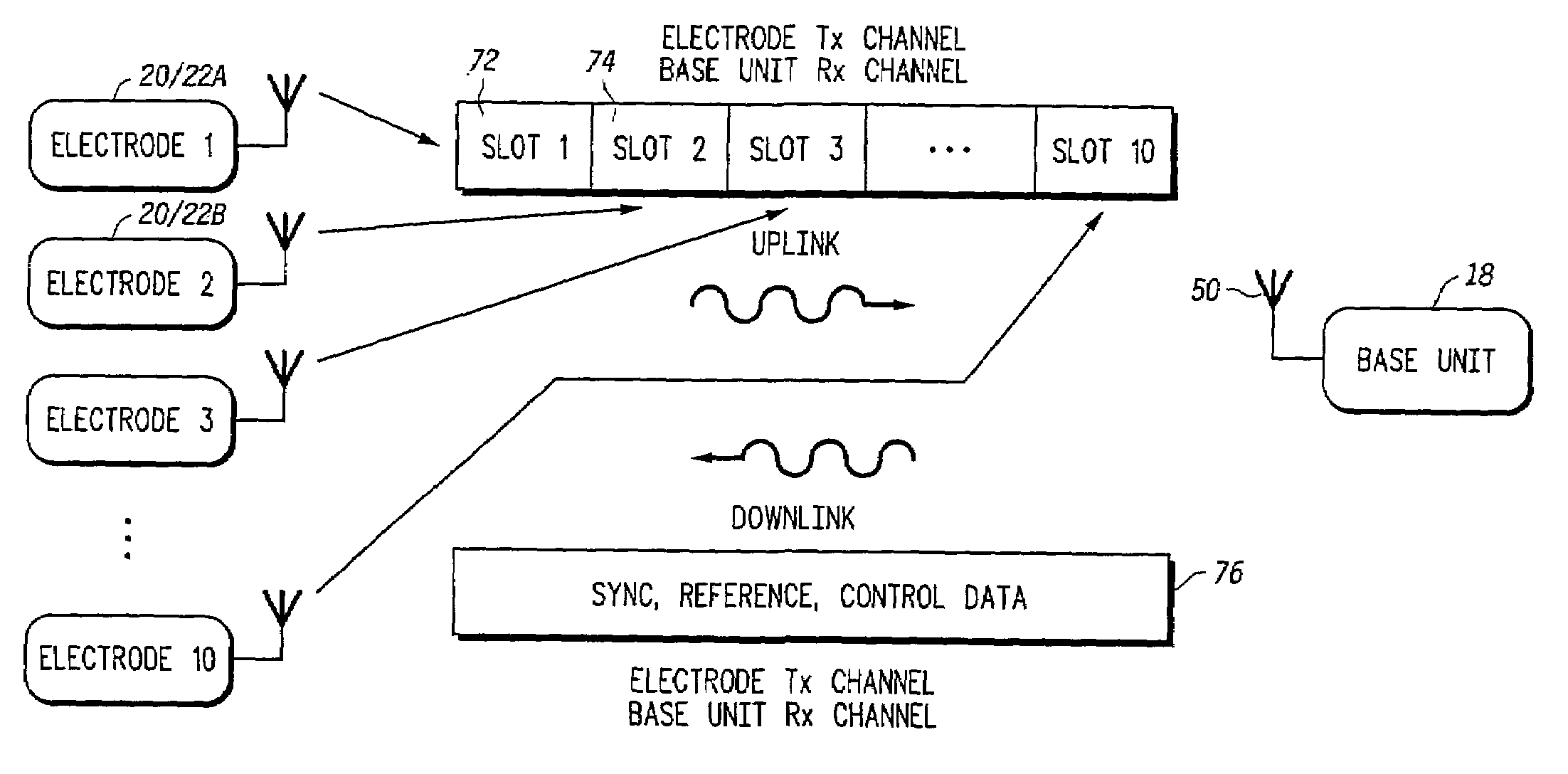
[0013]In a preferred embodiment, the wireless two-way communication between the base unit and the plurality of remotely programmable wireless transceivers is established in accordance with a protocol that provides for transmission of a variety of configuration commands. Examples of such commands include registration information, data acquisition control commands (such as start and stop messages), transmission frequency commands, time slot commands, amplifier gain commands, transmitter control commands, power saving mode commands, initialization commands, and so forth. The ability to remotely program the wireless transceivers gives considerable flexibility over how the electrodes are configured and positioned on the patient's body.

Problems solved by technology

The lengthy wired electrodes of conventional ECG apparatus obstruct the patient and limit the patient's freedom of movement.
They are also cumbersome for the physician or assisting nurse.
These systems are more expensive, intended for greater range (higher power), and do not totally eliminate the physical electrode wires attached to the patient.
Some telemetry systems also may not handle a 12 lead ECG (10 wires) because of the wiring that is required between the electrodes and the transmitter box.
However, the electrode patch is a special two-conductor type that is not conventional.
For the multiple electrode embodiment, the base unit contains multiple receivers and antennas which imply multiple transmit frequencies are required for the system and over-the-air signaling (thus making the base unit more costly to implement).

Method used


Image

  • Programmable wireless electrode system for medical monitoring
  • Programmable wireless electrode system for medical monitoring
  • Programmable wireless electrode system for medical monitoring

Examples


Embodiment Construction

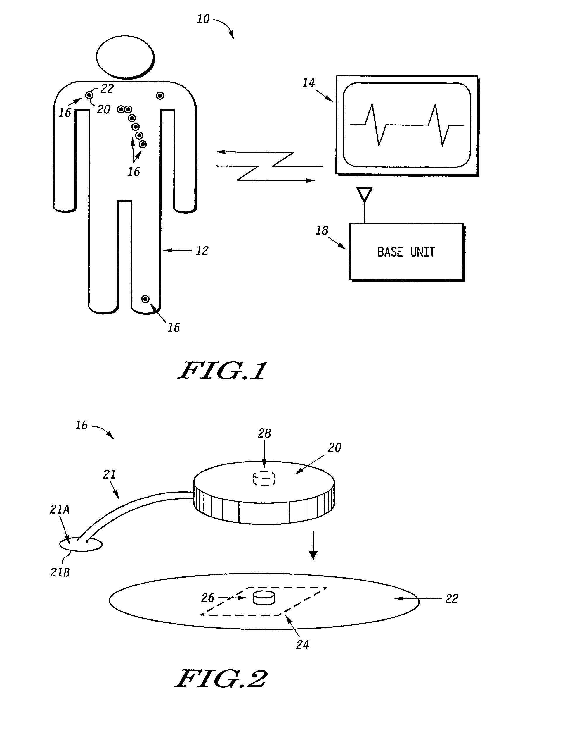
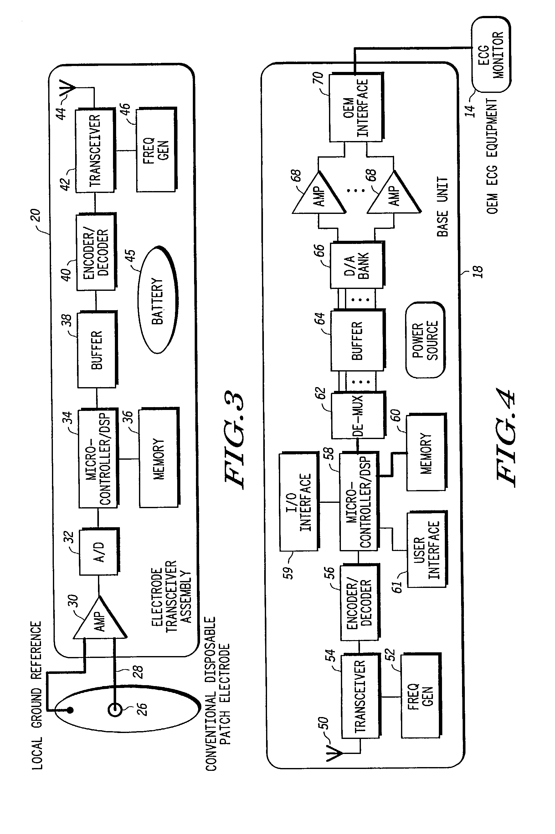
[0032]The present invention provides a system consisting of multiple smart wireless transceivers devices sized to snap onto conventional disposable patch electrodes for wireless medical monitoring, and a base unit communicating with the wireless electrode devices that is also capable of interfacing to existing conventional bedside monitoring and display equipment. The system is particularly suited to wireless ECG monitoring. The electrode devices receive commands from the base unit such as registration information, transmission frequency commands, amplifier gain commands, transmitter control commands, power saving mode, etc. and include hardware and software or firmware for processing these commands and responsively configuring the wireless transceivers accordingly.

[0033]The wireless transceivers will also preferably receive a global time base signal from the base unit. The global time base signal is used for in synchronizing the timing of acquisition of sample points for all electr...


PUM


Abstract

A wireless, programmable system for bio-potential signal acquisition (e.g., electrocardiogram (ECG) data) includes a base unit and a plurality of individual wireless, remotely programmable transceivers that connect to patch electrodes. The base unit manages the transceivers by issuing registration, configuration, data acquisition, and transmission commands using wireless techniques. Bio-potential signals from the wireless transceivers are demultiplexed and supplied via a standard interface to a conventional monitor for display.

Description

[0001]This application is a division of application Ser. No. 09 / 551,718, filed Apr. 18, 2000 now U.S. Pat. No. 6,496,705, which is hereby incorporated by reference herein.BACKGROUND OF THE INVENTION[0002]A. Field of the Invention[0003]This invention relates generally to the field of devices used to measure and display bio-potential signals generated by the body. More particularly, the invention relates to a plurality of wireless, remotely programmable electrode transceivers assemblies that are each coupled to a conventional patch electrode, and an associated base unit. The base unit obtains a patient's electrocardiogram (ECG) or other bio-potential signal from the wireless transceivers and supplies the signal to a monitor unit for display. The display may be a standard ECG monitor.[0004]B. Statement of Related Art[0005]Conventional ECG apparatus for hospital bedside monitoring typically requires up to ten wired electrodes. Each electrode is attached to the body of the patient, and h...

Claims


Application Information

Patent Timeline
IPC IPC(8): H04Q7/00A61B5/00A61B5/04A61B5/044A61B5/0476A61B5/0488A61N1/05A61N1/08H04B7/24H04W28/14H04W60/00H04W72/02H04W88/02
CPCA61B5/0006A61B5/6833A61N1/05H04L67/125A61N1/08A61B5/04085A61B2560/0412H04W28/14H04W60/00H04W72/02H04W88/02A61B5/282
Inventor NG, RICHARDLOPEZ, SALVADORKHAIR, MOHAMMADGHAEM, SANJAROLSON, WILLIAM L.
Owner LIFESYNC
Learn More