Method and system for utilizing waste

a waste and waste technology, applied in the field of waste methods and systems, can solve the problems of insufficient conventional arrangement for removing rejects and relatively high rejects, and achieve the effects of improving the quality of fibre material, maximizing the yield of fibres, and fine screening

Inactive Publication Date: 2006-01-24
VALMET TECH INC
View PDF11 Cites 8 Cited by
  • Summary
  • Abstract
  • Description
  • Claims
  • Application Information

AI Technical Summary

Benefits of technology

[0010]One object of the invention is to make it possible to recover a larger and higher quality portion than before of those fibres contained in waste which until now have been either passed to incineration or taken to a landfill site.
[0014]After slushing, the fibre suspension is course screened to remove the reject particles still remaining in it. In coarse screening, a perforated screen is used in which the diameter of holes is 2-4 mm, most advantageously about 3 mm. In that connection, pulp is sufficiently clean for the next process stage, which is usually centrifugal cleaning. The function of centrifugal cleaning is to remove sand and other heavy particles from the pulp. After that, the pulp is fine screened and possibly fractionated for various uses. As there is an abundance of relatively inexpensive raw material available, in the fibre recovery line according to the invention there is no need to attempt to maximise the yield of fibres, as in conventional recycling processes, but the quality of fibres can be optimised. Thus, fine screening can be enhanced and the amount of reject increased as compared with conventional fibre recovery processes. Disposal of the increased reject volume presents no problem because said reject can be combusted together with the rejects derived from slushing and coarse screening.
[0015]After fine screening, the pulp is washed to improve the quality of the end product. Advantageously, the washed pulp is compressed in the end to a dry matter content of about 50%, after which it is ready for transport to a site of use situated at a reasonable distance. Alternatively, the pulp can be dried for transport to a dry matter content of about 90% or delivered as wet to a paper or board machine located in the immediate vicinity.
[0016]The fibre recovery process according to the invention consumes a considerable amount of water, which makes it necessary to clean and recirculate the process waters. The waste waters produced in different process stages are collected, treated and returned to the process. Cleaning can be accomplished, for example, as biological treatment, which is followed by clarification and, when needed, by further treatment stages for part of the water amount. The clean water necessary for the water balance of the system is introduced into the pulp washing stage at which it improves the quality of the end product.
[0019]The method described above, in which fine screening is enhanced to improve the quality of fibre material and the reject portion increased as a result of it is passed to the energy production of the plant, is also particularly advantageous in the stock circulation of paper and board machines, in particular of OCC board machines, also when recycled fibre pulp is used as raw material. Today, to maximize the yield of fibres, the reject from screening is returned to the main stock flow, in which connection poor material circulates in the process. As a result of this, the runnability of the paper or board machine deteriorates and the quality of the end product decreases. Optimisation of fine screening and passing of the reject to the boiler of the mill offer a new possibility of optimising the quality of the end product in an economical manner.

Problems solved by technology

As the amount of reject is relatively high when slushing mixed waste, conventional arrangements for removal of reject are not sufficient.

Method used


Image

  • Method and system for utilizing waste
  • Method and system for utilizing waste

Examples


Embodiment Construction

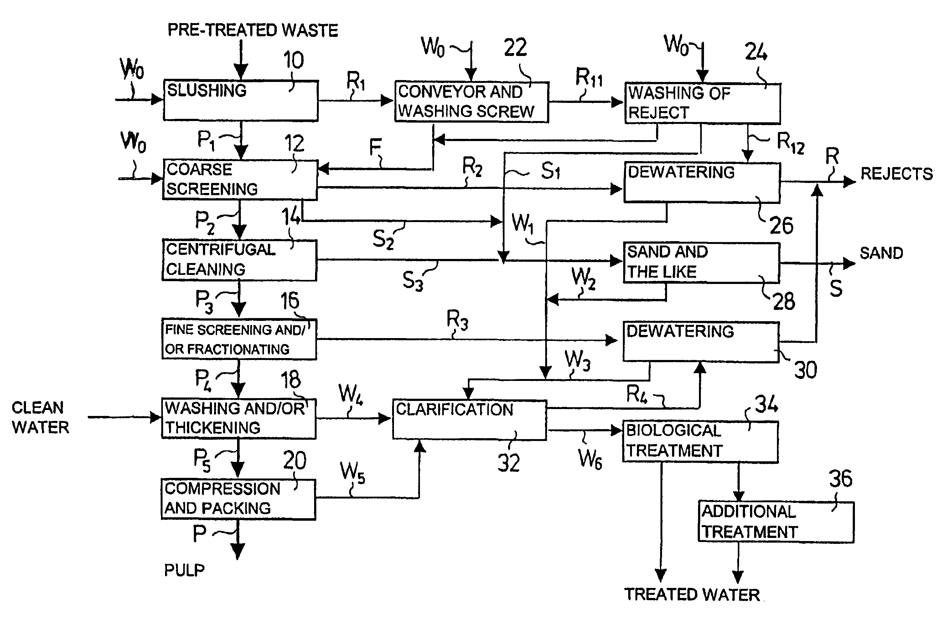
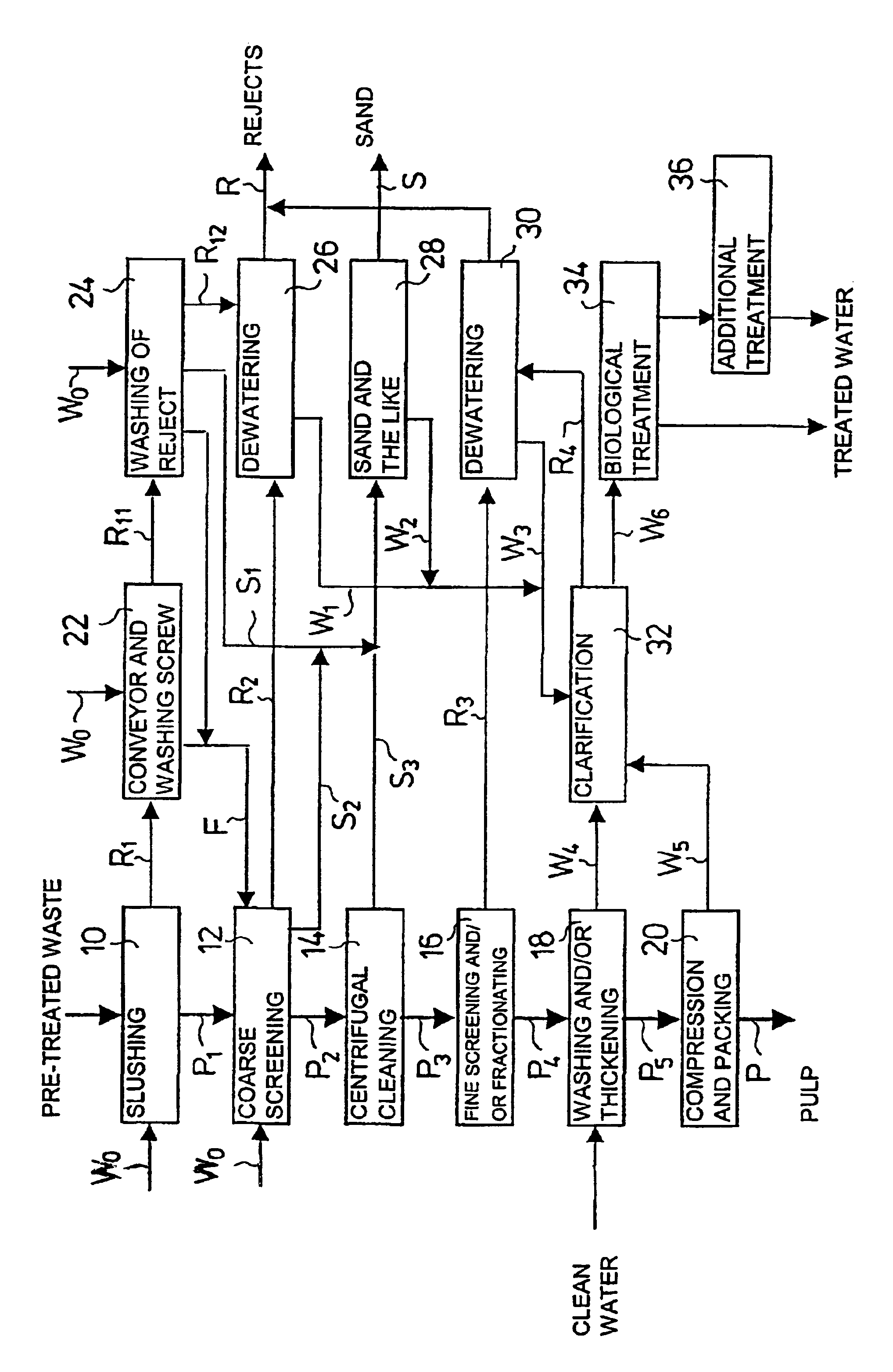
[0021]Pre-treated waste is passed to a fibre separation process, which waste has been crushed and screened and from which non-combustible and undesirable fractions, such as metal, glass, stones, biowaste, etc. have been removed. The waste material is slushed in a continuous-operation high-consistency pulper 10, advantageously at a temperature of about 60° C. A material stream P1 containing fibres suspended in water and a material stream R1 containing non-defibrable waste are discharged substantially continuously from the pulper 10. A screw conveyor 22 moves the reject fraction R1 from the pulper 10 into a combined washing and drying drum 24 of the reject. The reject is washed by means of circulation water W0 both on the screw conveyor 22 and in the washing drum 24, and fibre-containing washing waters F are returned to be mixed with the fibre suspension P1.

[0022]The fibre fraction P1 taken out of the pulper 10 through a screen plate is passed to coarse screening 12, in which coarse i...


PUM

PropertyMeasurementUnit
temperatureaaaaaaaaaa
diameteraaaaaaaaaa
diameteraaaaaaaaaa

Abstract

Waste that contains fibers and combustible material is slushed in a continuous-operation high-consistency pulper (10) to suspend in water the fibers contained in the waste. From the pulper (10) are discharged substantially continuously a fiber suspension (P1) through a screen plate; and non-defibrable material (R1) by means of a mechanical transfer device (22). The fiber suspension (P1) is sorted and cleaned for use as raw material in paper or board. The non-defibrable material (R1) and the rejects (R2-R4) separated from the fiber suspension (P1) in the sorting and cleaning stages are used as fuel in energy production and / or utilized as raw material.

Description

CROSS REFERENCES TO RELATED APPLICATIONS[0001]This application is a U.S. national stage application of International Application No. PCT / FI01 / 00494, filed May 22, 2001, and claims priority on Finnish Application No. 20001218 filed May 22, 2000, the disclosures of both of which applications are incorporated by reference herein.STATEMENT AS TO RIGHTS TO INVENTIONS MADE UNDER FEDERALLY SPONSORED RESEARCH AND DEVELOPMENT[0002]Not applicable.BACKGROUND OF THE INVENTION[0003]The invention relates to a method and system for utilizing waste that contains fibres and combustible material. In addition, the invention relates to a method for processing fibre in a paper or board mill that utilizes recycled fibre pulp.[0004]Conventionally, the options available in waste disposal and processing have been: transport to landfill sites, incineration in mass incineration plants and—to a limited extent—recovery of recyclable materials. The last-mentioned option generally requires separation of wastes at...

Claims


Application Information

Patent Timeline
Patent Type & Authority Patents(United States)
IPC IPC(8): B02C23/36B03B9/06B09B5/00B09B3/00D21B1/02D21B1/32D21B1/34D21C5/02D21D5/00
CPCB03B9/061D21C5/02D21B1/32D21B1/026Y02W30/64B09B3/00
Inventor HAUTALA, JOUKO
Owner VALMET TECH INC
Why Eureka
Try Eureka