Biomass gasifycation furnace and system for methanol synthesis using gas produced by gasifying biomass

a gasification furnace and biomass technology, applied in the direction of furnaces, physical/chemical process catalysts, combustible gas purification/modification, etc., can solve the problems of low biomass utilization, low yield, and thus produced gas cannot serve as a raw material for methanol synthesis

Inactive Publication Date: 2006-01-31
MITSUBISHI HEAVY IND LTD
View PDF22 Cites 61 Cited by
  • Summary
  • Abstract
  • Description
  • Claims
  • Application Information

AI Technical Summary

Benefits of technology

[0109]A seventy-fourth mode is drawn to a biomass feeding unit as described in relation to the seventieth mode, wherein a plurality of injection nozzles are radially provided at the distal end portion of the casing, and gas is injected through the nozzles to the granular material which has arrived as conveyed through the screw feeder while being compressed and constrained between adjacent walls of the screw flight of the screw feeder, to thereby eliminate compression and entanglement of the granular material and discharge the granular material downward through the outlet.
[0110]A seventy-fifth mode is drawn to a biomass feeding unit as described in relation to the seventieth mode, wherein a screw shaft of the screw feeder is formed of a hollow member, and a perforation penetrating the screw shaft from the outer circumferential surface to the interior thereof, or an injection nozzle utilizing the perforation, is provided between adjacent walls of the screw flight in the vicinity of the distal end portion of the screw feeder, and gas is injected through the perforation or injection nozzle to the granular material which has arrived as conveyed through the screw feeder while being compressed and constrained between adjacent walls of the screw flight of the screw feeder, to thereby eliminate compression and entanglement of the granular material and discharge the granular material downward through the outlet.
[0111]A seventy-sixth mode is drawn to a biomass feeding unit as described in relation to the seventieth mode, further comprising a fluidization cone for receiving the granular material discharged and falling through the outlet, and imparting a gyratory flow to the granular material to thereby eliminate entanglement of the granular material, and gas forming the gyratory flow is utilized as a carrier gas for feeding the granular material to a destination apparatus such as a gasification furnace.
[0116]An eighty-first mode is drawn to a biomass feeding unit characterized by comprising a hollow cylindrical hopper for storing granular material such as fibrous granular biomass obtained by finely pulverizing biomass, the hopper including stirring means for stirring the granular material; and a screw feeder for conveying the granular material in a horizontal direction, the feeder being provided at the lower portion of the hopper, wherein the diameter of the distal end portion of the screw feeder is gradually reduced and the distal end thereof is connected to a feeding line having a small diameter; and gas is injected, at the distal end portion of the screw feeder, to the granular material which is compressed by and conveyed through the screw feeder, to thereby loosen compression and eliminate entanglement of particles of the granular material, and the resultant granular material is conveyed and fed, through the feeding line, by a carrier gas stream of the aforementioned gas to a destination apparatus such as a gasification furnace.

Problems solved by technology

The former method, the fermentation method, requires installation of a tank for sugar components, whereas the hydrothermal degradation method involves the problems that high temperature and high pressure are required and yet yield is low.
Moreover, another problem is that, considerable amounts of residue are generated from the input biomass, raising the problem of low biomass utilization.
However, since only the surface portions of granular biomass undergo reaction, and the reaction cannot proceed uniformly to the innermost portion of the granules, tar is generated, and the produced gas; i.e., the gas obtained through gasification, has a low H2 content and low CO content.
Therefore, the thus-produced gas cannot serve as a raw material for methanol synthesis.
Moreover, the generated tar is deposited not only onto the inside wall of the furnace, but also onto the apparatuses, etc. installed on the downstream side of the furnace, inviting problematic maloperation of the furnace.
However, in this case, another problem is involved; a high-temperature zone of higher than 1,200° C. is formed at some portions, where gasification of biomass does not proceed successfully, providing large amounts of soot through combustion of biomass.

Method used


Image

  • Biomass gasifycation furnace and system for methanol synthesis using gas produced by gasifying biomass
  • Biomass gasifycation furnace and system for methanol synthesis using gas produced by gasifying biomass
  • Biomass gasifycation furnace and system for methanol synthesis using gas produced by gasifying biomass

Examples


tenth embodiment

[Tenth Embodiment]

[0283]A tenth embodiment will next be described with reference to FIG. 10.

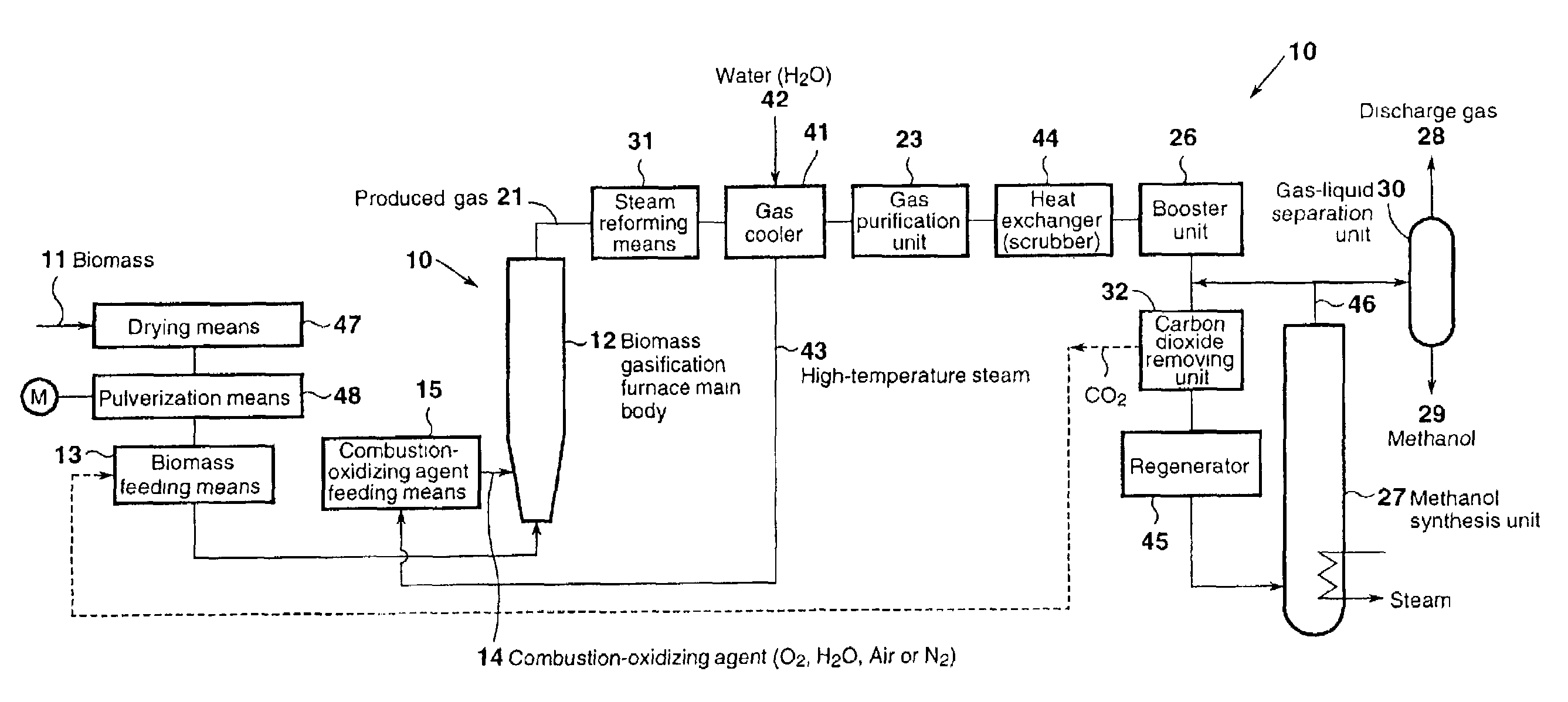
[0284]FIG. 10 is a schematic diagram of a methanol synthesis system making use of a gas produced through gasification performed in a biomass gasification furnace according to the tenth embodiment.

[0285]Components having the same functions as those in the aforementioned methanol synthesis system are denoted by the same reference numerals, and repeated descriptions of such components are omitted.

[0286]As shown in FIG. 10, in the methanol synthesis system according to the tenth embodiment, the heat exchanger 44 for cooling the gas purified by the gas purification unit 26 and for removing moisture in the gas, comprises a water sprinkling means 44A for sprinkling water 76; and an alkaline water sprinkling means 44B for sprinkling alkaline solution 77 (e.g., NaOH). Heat recovery is carried out in a manner similar to that employed in the ninth embodiment, employing discharge water 71 resulting from ...

eleventh embodiment

[Eleventh Embodiment]

[0290]A eleventh embodiment of the present invention will be described with reference to FIG. 11.

[0291]FIG. 11 is a schematic diagram of a methanol synthesis system making use of a gas produced through gasification performed in a biomass gasification furnace according to the eleventh embodiment.

[0292]Components having the same functions as those in the aforementioned methanol synthesis system are denoted by the same reference numerals, and repeated descriptions of such components are omitted.

[0293]The methanol synthesis system according to the present embodiment includes a first adsorption column or guard column 78 provided between the aforementioned booster unit 26 and regenerator 45 in the methanol synthesis system; and a second adsorption column or guard column 79 provided between the aforementioned regenerator 45 and methanol synthesis unit 27.

[0294]The aforementioned adsorption columns are filled with a substance having adsorption capability, such as silica...

twelfth embodiment

[Twelfth Embodiment]

[0297]A twelfth embodiment of the present invention will be described with reference to FIG. 12.

[0298]FIG. 12 is a schematic diagram of a methanol synthesis system making use of a gas produced through gasification performed in a biomass gasification furnace according to the twelfth embodiment.

[0299]Components having the same functions as those in the aforementioned methanol synthesis system are denoted by the same reference numerals, and repeated descriptions of such components are omitted.

[0300]The methanol synthesis system according to the twelfth embodiment effectively utilizes H2 contained in discharge gas 28 which has been separated through gas / liquid separation of the gas 46 produced in a methanol synthesis unit 27.

[0301]As shown in FIG. 12, the produced gas 46 synthesized by the aforementioned methanol synthesis unit 27 is separated into methanol 29 and discharge gas 28 by means of a gas / liquid separation unit 30. Generally, the discharge gas 28 is fed bac...


PUM

PropertyMeasurementUnit
temperatureaaaaaaaaaa
superficial velocityaaaaaaaaaa
pressureaaaaaaaaaa

Abstract

Methanol is synthesized from a gas produced through gasification of biomass serving as a raw material, making use of a biomass feeding means for feeding biomass into a furnace main body and, located above the biomass feeding means, combustion-oxidizing-agent-feeding means for feeding into the furnace main body a combustion-oxidizing agent containing oxygen or a mixture of oxygen and steam.

Description

[0001]This application is the national phase under 35 U.S.C. §371 of PCT International Application No. PCT / JP01 / 01390 which has an International filing date of Feb. 26, 2001, which designated the United States of America and was not published in English.TECHNICAL FIELD[0002]The present invention relates to a biomass gasification furnace, and to a methanol synthesis system making use of a gas produced through biomass gasification.BACKGROUND ART[0003]The word biomass generally refers to substances of biological origin (e.g., agricultural products or by-products; lumber; plants; etc.) that can be utilized as an energy source or industrial raw material. Since biomass is produced by solar energy, and by the action of air, water, soil, or similar natural substances, it can be produced infinitely.[0004]Fuel, methanol, and similar materials can be produced making use of the above-described biomass. Also, since biomass that exists in the form of waste can be utilized, a clean environment can...

Claims


Application Information

Patent Timeline
Patent Type & Authority Patents(United States)
IPC IPC(8): B01J8/00C07C29/152C10J3/00C10J3/50
CPCC07C29/152C10J3/506C10K1/004C10K1/005C10K1/08C10K1/101C10K1/12C10K1/122C10K1/143C10K3/04C10K3/006C10K3/023C10J3/485C10J3/84C07C31/04C10J2200/158C10J2300/0916C10J2300/0956C10J2300/0973C10J2300/1665C10J2300/1807Y02E50/18Y02P20/145Y02E50/10Y02P20/133C10J3/00
Inventor KANEKO, SHOZOSATO, SUSUMUKOBAYASHI, YOSHINORIKABATA, TATSUOKOBAYASHI, KAZUTOTAKEUCHI, YOSHIYUKITOKUDA, KIMISHIROHASHIMOTO, AKIRASHINODA, KATSUHIKOTAKENO, KEIJIMATSUMOTO, SHINJIOHTA, HIDEAKIYAMAMOTO, TSUGIOSAKAI, MASAYASUTAKEGAWA, TOSHIYUKISEIKE, YAJYURO
Owner MITSUBISHI HEAVY IND LTD
Why Eureka
Try Eureka