Capacitive sensor

a capacitive sensor and fluid pressure technology, applied in the direction of variable capacitors, instruments, force/torque/work measurement apparatus, etc., can solve the problems of difficult and expensive fabrication, large mass of attached metal plates, and introduction of measurement errors in diaphragms, etc., to reduce the effect of diode conduction, easy fabrication, and compact structur

Inactive Publication Date: 2006-01-31
WELCH ALLYN INC
View PDF12 Cites 21 Cited by
  • Summary
  • Abstract
  • Description
  • Claims
  • Application Information

AI Technical Summary

Benefits of technology

[0010]The present invention relates to a capacitive sensor that is compact, inexpensive and easily fabricated using commonly available components. The capacitive sensor of the present invention is less susceptible to errors caused by vibration, acceleration, or its orientation to the earth's gravitational field. The capacitive sensor of the present invention includes an improved oscillator circuit that reduces the effects of diode conduction without the errors of the conventional design. Thus, the output of the sensor of the present invention does not substantially drift over temperature.

Problems solved by technology

There are several problems with the conventional approach.
Fabrication is difficult and expensive.
The use of a metal plate attached to a diaphragm introduces measurement errors if the planar surface of the attached plate is not parallel to the planar surface of the fixed plate.
Further, the attached metal plate has a relatively large mass.
The biggest problem with the circuit depicted in FIG. 1 is the conduction of the input protection diodes of the threshold detector stage G1.
However, as R3 reduces diode errors, it amplifies errors introduced by other components in the oscillator.
The direct effect is increased sensitivity to changes in capacitance of the internal circuit at the input of gate G1, thus affecting frequency stability.
The conventional design has other problems as well.

Method used


Image

  • Capacitive sensor
  • Capacitive sensor
  • Capacitive sensor

Examples


second embodiment

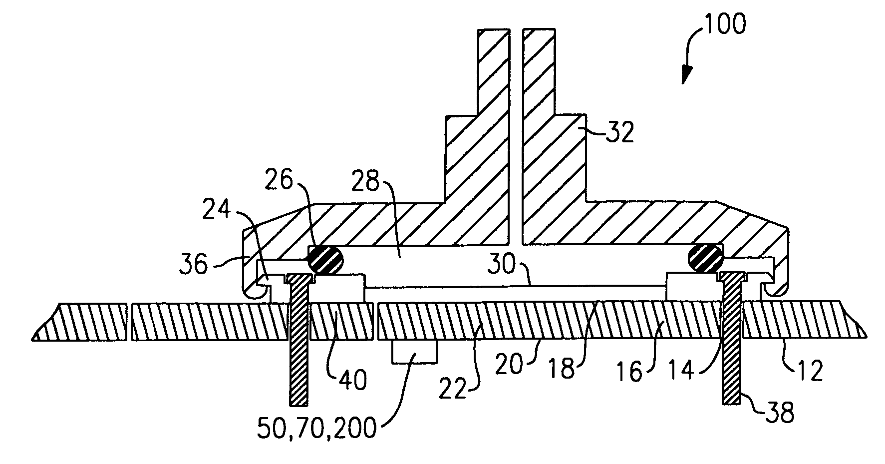
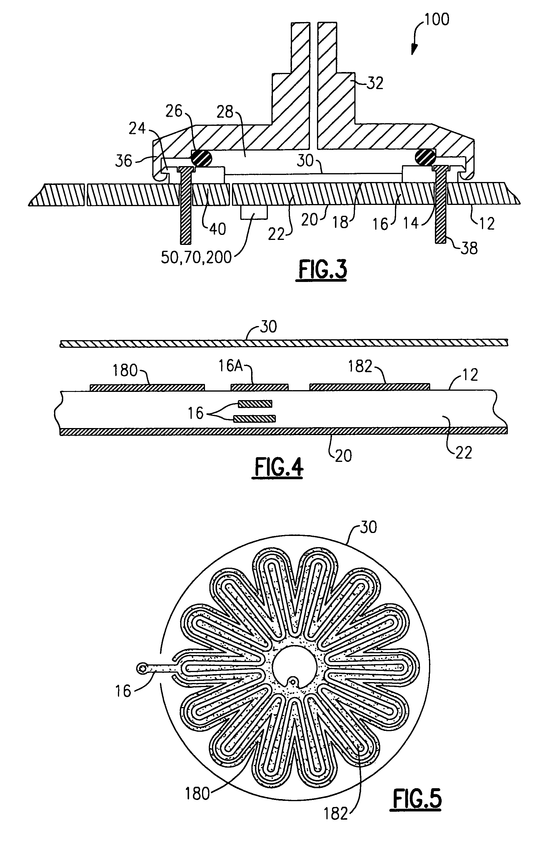
[0040]As embodied herein and depicted in FIG. 4, a cross-sectional view of an electrode configuration in capacitive pressure sensor transducer 100 in accordance with the present invention is disclosed. Printed circuit board 12 is used as the substrate. Circuit board 12 is fabricated using dielectric material 22. Ground layer 20 is disposed on the under-side of circuit board 12. Ground rings 16 are disposed within dielectric mater 22. Outer electrode 180 and inner electrode 182 are co-planar, enclosing ground conductor 16A within the plane of the top-side of circuit board 12. Metallic diaphragm 30 is a ground third electrode in capacitive sensor transducer 100. FIG. 5 is a plan view of the electrode configuration depicted in FIG. 4. As shown, electrode 180 and electrode 182 are arranged in a spiral, serpentine, and / or interdigitated pattern to maximize inter-electrode capacitance. As shown by the “footprint” of diaphragm 30, diaphragm 30 covers the entire area of the co-planar electr...

third embodiment

[0053]FIG. 9 is a schematic of an improved three-inverter oscillator circuit in accordance with a third embodiment the present invention. This embodiment is identical to the embodiment depicted in FIG. 6, except that gate 56A is disposed in parallel with gate 56. In similar embodiments, gate 56A includes a plurality of gates in parallel with gate 56. Gate 56A functions to reduce the errors caused by changes in the output resistance of gate 56.

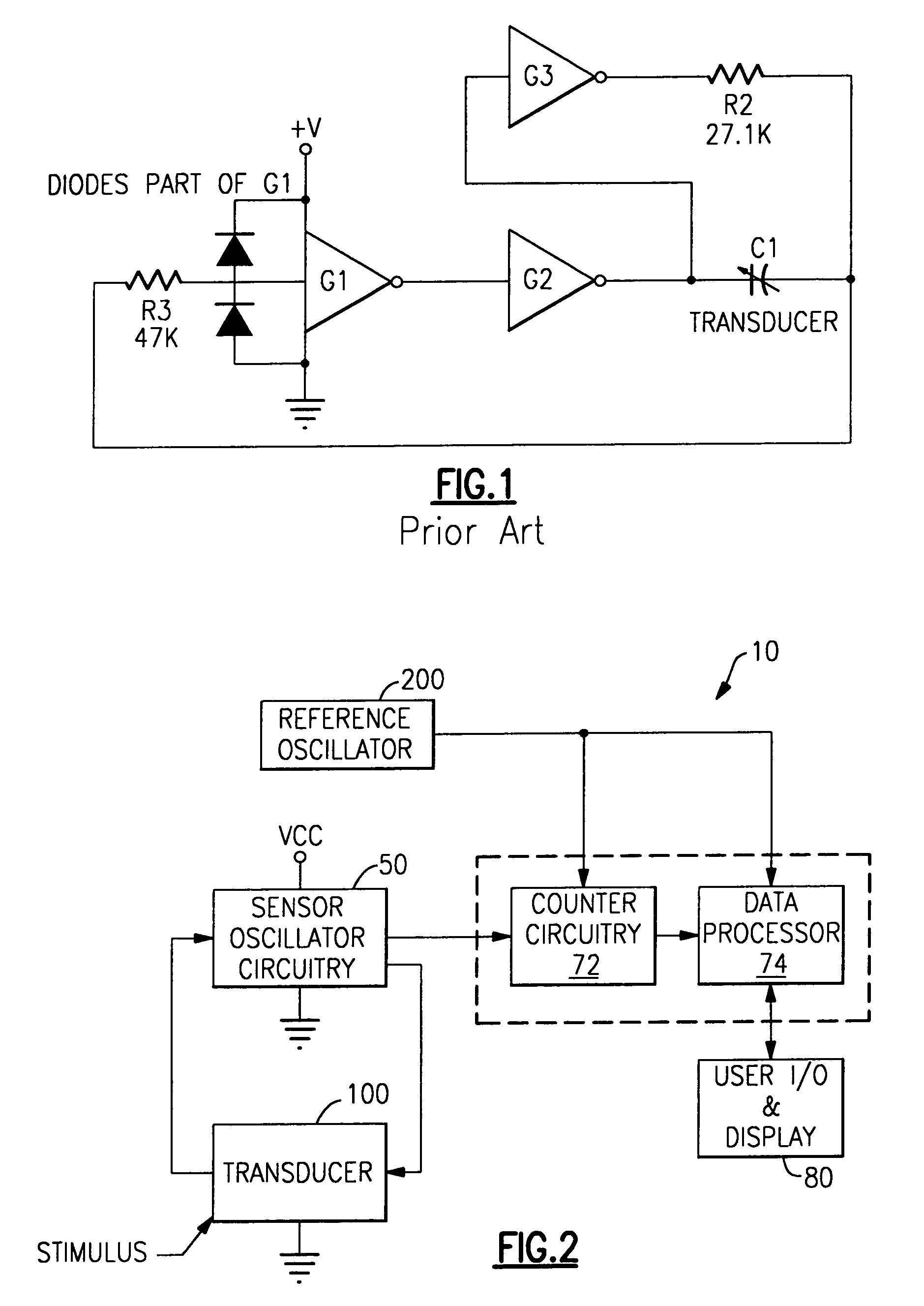
[0054]As shown in FIG. 6, FIG. 8, and FIG. 9, oscillator circuit 50 is connected to measurement / processing circuit 70, which includes counter 72. The method of counting the pulses from the oscillator is not important as long as it can measure the frequency with adequate resolution. The most straightforward methods are Frequency Counting and Period Averaging.

fourth embodiment

[0055]As embodied herein and depicted in FIG. 10, a block diagram of counter circuit 72 in accordance with a fourth embodiment the present invention is disclosed. In this embodiment, the frequency counting method is employed. Counter circuit 72 includes pulse counter 720 and gate generator 722. Gate generator 722 provides counter 720 with an enablement pulse with width Tgate. The frequency counting method counts the pulses from sensor oscillator 50 during a fixed interval of time Tgate, yielding a number N. The frequency of the result is then N / Tgate. This is very simple and economical, but requires a long time to obtain a given resolution. This can be improved by increasing the frequency of operation of sensor oscillator 50, but at a cost of larger drift errors in sensor oscillator 50 as the delay of the gates becomes more dominant in determining the frequency.


PUM

PropertyMeasurementUnit
dielectric constantaaaaaaaaaa
capacitanceaaaaaaaaaa
frequencyaaaaaaaaaa

Abstract

A capacitive sensor is disclosed that includes a variable capacitor transducer that varies its capacitance with changes in an environmental parameter. The present invention is adapted to measure any linear parameter such as pressure, force, or distance. The sensor of the present invention is compact, inexpensive to make, and easily fabricated using commonly available components. Furthermore, it is not susceptible to errors caused by vibration, acceleration, and its orientation to the earth's gravitational field. The output of the capacitive sensor does not substantially drift with changes in temperature.

Description

CROSS-REFERENCE TO RELATED APPLICATIONS[0001]This is a continuation of Ser. No. 10 / 058,191, filed Oct. 26, 2001, now U.S. Pat. No. 6,828,801, which is herein incorporated by reference in its entirety.BACKGROUND OF THE INVENTION[0002]1. Field of the Invention[0003]The present invention relates generally to fluid pressure sensors, and particularly to capacitive fluid pressure sensors.[0004]2. Technical Background[0005]Capacitive sensors are used widely in a variety of medical and industrial applications to measure linear parameters such as force and pressure. For example, capacitive pressure sensors are used in blood pressure products. They can also be used to measure air or other fluid pressures.[0006]In the conventional approach, the capacitive pressure sensor includes a pressure sensor assembly coupled to an electronic circuit. The pressure sensor assembly includes a port that connects the sensor to the environment. The sensor itself is constructed using a variable capacitor. In th...

Claims


Application Information

Patent Timeline
Patent Type & Authority Patents(United States)
IPC IPC(8): G01R27/26H01G7/00G01L7/08G01L9/00G01L9/12
CPCG01D5/2417G01L9/0044G01L9/12G01L9/0072
Inventor BURDICK, KENNETHLIA, RAYMOND A.VIVENZIO, ROBERT L.
Owner WELCH ALLYN INC
Why Eureka
Try Eureka