High fill ratio reflective spatial light modulator with hidden hinge

Inactive Publication Date: 2006-01-31
MIRADIA INC
View PDF64 Cites 88 Cited by
  • Summary
  • Abstract
  • Description
  • Claims
  • Application Information

AI Technical Summary

Benefits of technology

[0014]Because the hinge and the mirror plate are in the same substrate (i.e., in the same layer), there is no translational movement or displacement as the mirror rotates about the longitudinal axis of the hinge. With no translational displacement, the gap between the mirrors and the support walls are limited only by the fabrication technology and process. The close spacing of the mirror plates and the hiding of by positioning the hinge substantially beneath the reflective surface allow for a high fill ratio for the micro mirror array, improved contrast ratio, minimized scattering and diffraction of light, and virtual elimination of light passing through the micro mirror array to strike the circuitry on the second substrate.
[0015]Further, because the mirror plate and t

Problems solved by technology

With no translational displacement, the gap between the mirrors and the

Method used


Image

  • High fill ratio reflective spatial light modulator with hidden hinge
  • High fill ratio reflective spatial light modulator with hidden hinge
  • High fill ratio reflective spatial light modulator with hidden hinge

Examples


Embodiment Construction

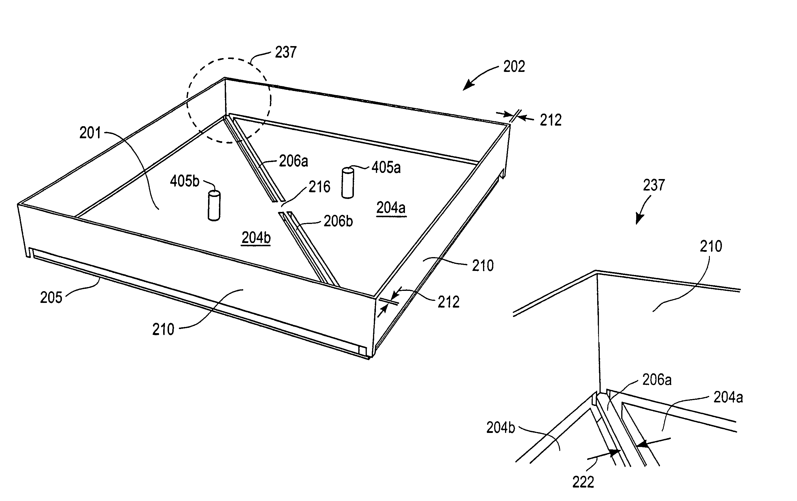
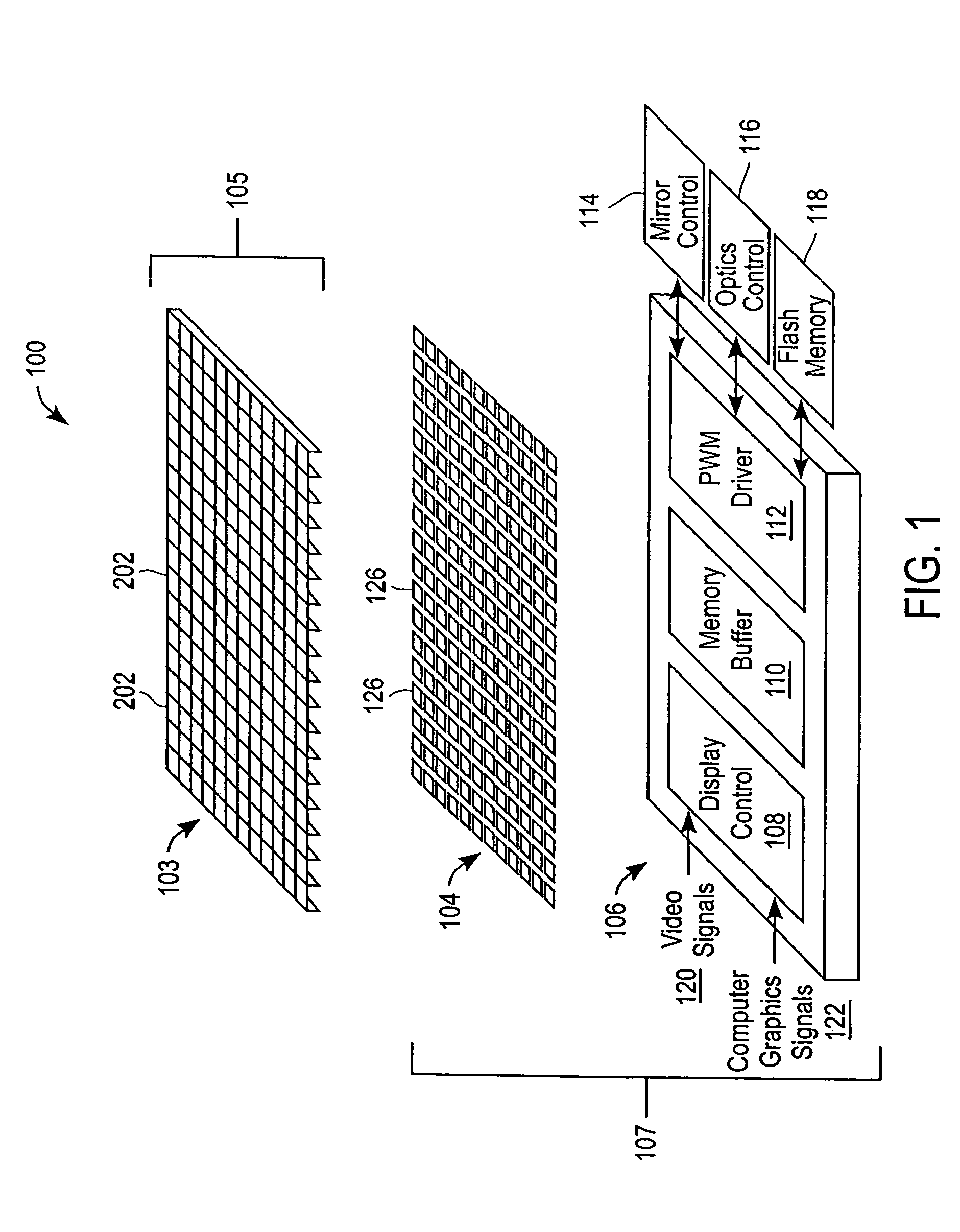
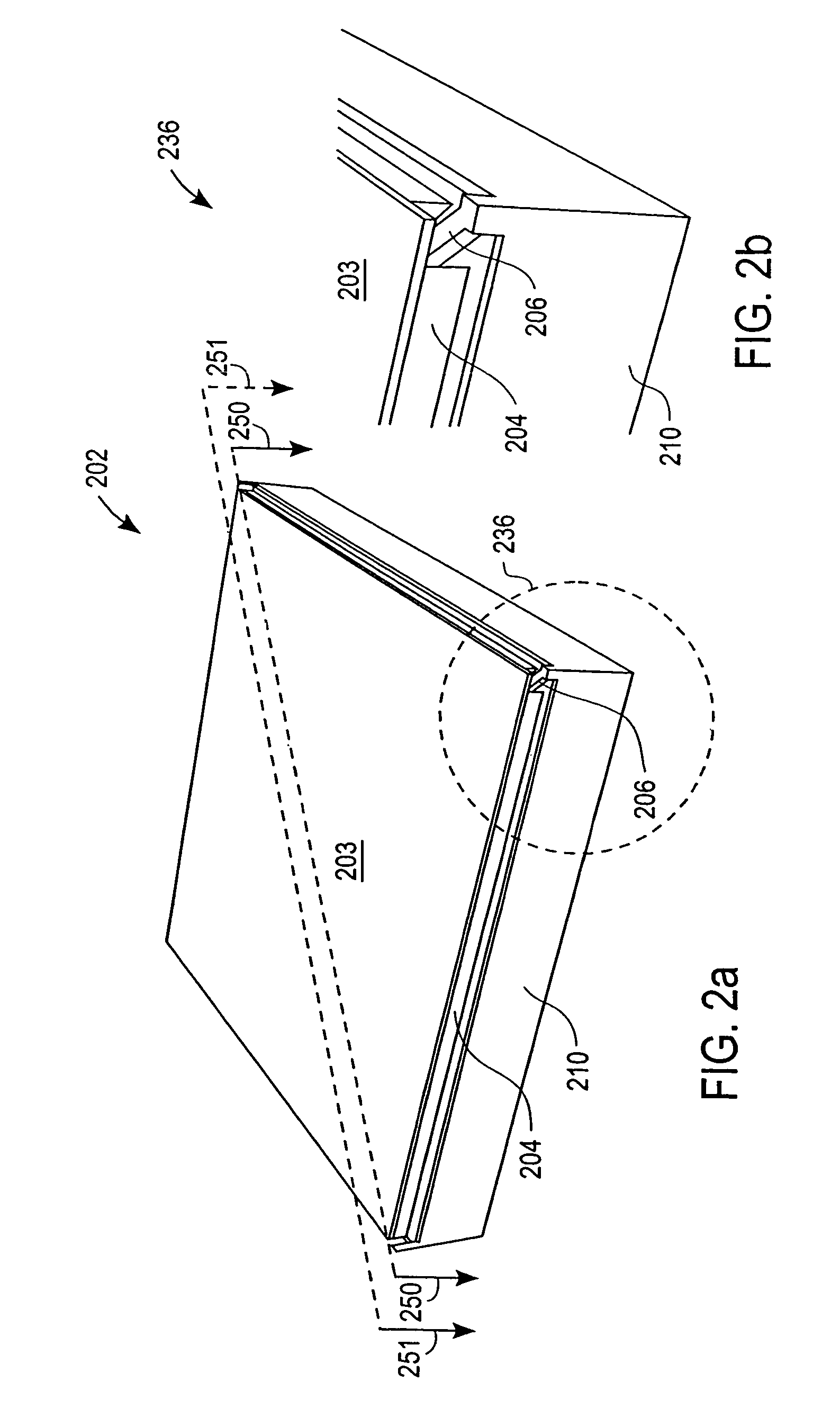
[0035]The reflective spatial light modulator (“SLM”) 100 has an array 103 of deflectable mirrors 202. Individual mirrors 202 can be selectively deflected by applying a voltage bias between that mirror 202 and a corresponding electrode 126. The deflection of each mirror 202 controls light reflected from a light source to a video display. Thus, controlling the deflection of a mirror 202 allows light striking that mirror 202 to be reflected in a selected direction, and thereby allows control of the appearance of a pixel in the video display.

[0036]Spatial Light Modulator Overview:

[0037]FIG. 1 is a schematic diagram that illustrates the general architecture of an SLM 100 according to one embodiment of the invention. The illustrated embodiment has three layers. The first layer is a mirror array 103 that has a plurality of deflectable micro mirrors 202. In one preferred embodiment, the micro mirror array 103 is fabricated from a first substrate 105 that is a single material, such as single...


PUM


Abstract

A micro mirror array having a hidden hinge that is useful, for example, in a reflective spatial light modulator. In one embodiment, the micro mirror array includes spacer support walls, a hinge, a mirror plate and a reflective surface on the upper surface of the mirror plate, the reflective surface concealing the hinge and the mirror plate. The micro mirror array fabricated from a single material.

Description

CROSS-REFERENCE TO RELATED APPLICATION[0001]The present application is a continuation of application Ser. No. 10 / 611,121, “High Fill Ratio Reflective Spatial Light Modulator with Hidden Hinge,” filed Jun. 30, 2003 now abandoned, which claims priority from provisional U.S. Patent Application Ser. No. 60 / 475,404, for “Hidden Hinge High Fill Ratio Reflective Spatial Light Modulator,” filed Jun. 2, 2003, the disclosure of which is incorporated by reference. This application also is a continuation-in-part of application Ser. No. 10 / 378,056, for “Reflective Spatial Light Modulator,” filed Feb. 27, 2003 now abandoned, the disclosure of which is incorporated by reference, which claims the benefit of provisional U.S. Patent Application Ser. No. 60 / 390,389, for “Reflective Spatial Light Modulator,” filed Jun. 19, 2002. This application also is a continuation-in-part of application Ser. No. 10 / 378,041, for “Fabrication of a Reflective Spatial Light Modulator,” filed Feb. 27, 2003 now abandoned...

Claims


Application Information

Patent Timeline
IPC IPC(8): G02B26/00G02B26/08
CPCG02B26/0841
Inventor PAN, SHAOHER XYANG, XIAO
Owner MIRADIA INC
Why Eureka
Try Eureka