Light source device and wavelength control device therefor

a technology of wavelength control device and light source device, which is applied in the direction of active medium material, semiconductor laser arrangement, semiconductor laser, etc., can solve the problems of complicated configuration of wavelength control device to be used in combination with tunable laser, increase in number, etc., and achieve the effect of easy wavelength control

Inactive Publication Date: 2006-02-07
FUJITSU LTD
View PDF12 Cites 8 Cited by
  • Summary
  • Abstract
  • Description
  • Claims
  • Application Information

AI Technical Summary

Benefits of technology

[0010]It is therefore an object of the present invention to make wavelength control easy in a light source device applicable to WDM.
[0012]For example, the control loop may comprise an optical filter optically coupled to the plurality of laser diodes and having a transmittance substantially periodically changing with wavelength, and means for controlling the temperatures of the plurality of laser diodes so that the intensity of transmitted light through the optical filter becomes constant. In this case, by the compensation of the temperature control conditions, the oscillation wavelength of each laser diode can be easily stabilized to each wavelength channel of WDM with a wavelength control device having a simple configuration, thus achieving one of the objects of the present invention.

Problems solved by technology

In the case that the number of WDM channels is further increased in the future, the kind of spare light sources may increase in number, causing a serious problem.
However, there is a problem that a wavelength control device to be used in combination with this tunable laser becomes complicated in configuration.

Method used


Image

  • Light source device and wavelength control device therefor
  • Light source device and wavelength control device therefor
  • Light source device and wavelength control device therefor

Examples


Embodiment Construction

[0025]Some preferred embodiments of the present invention will now be described in detail with reference to the attached drawings.

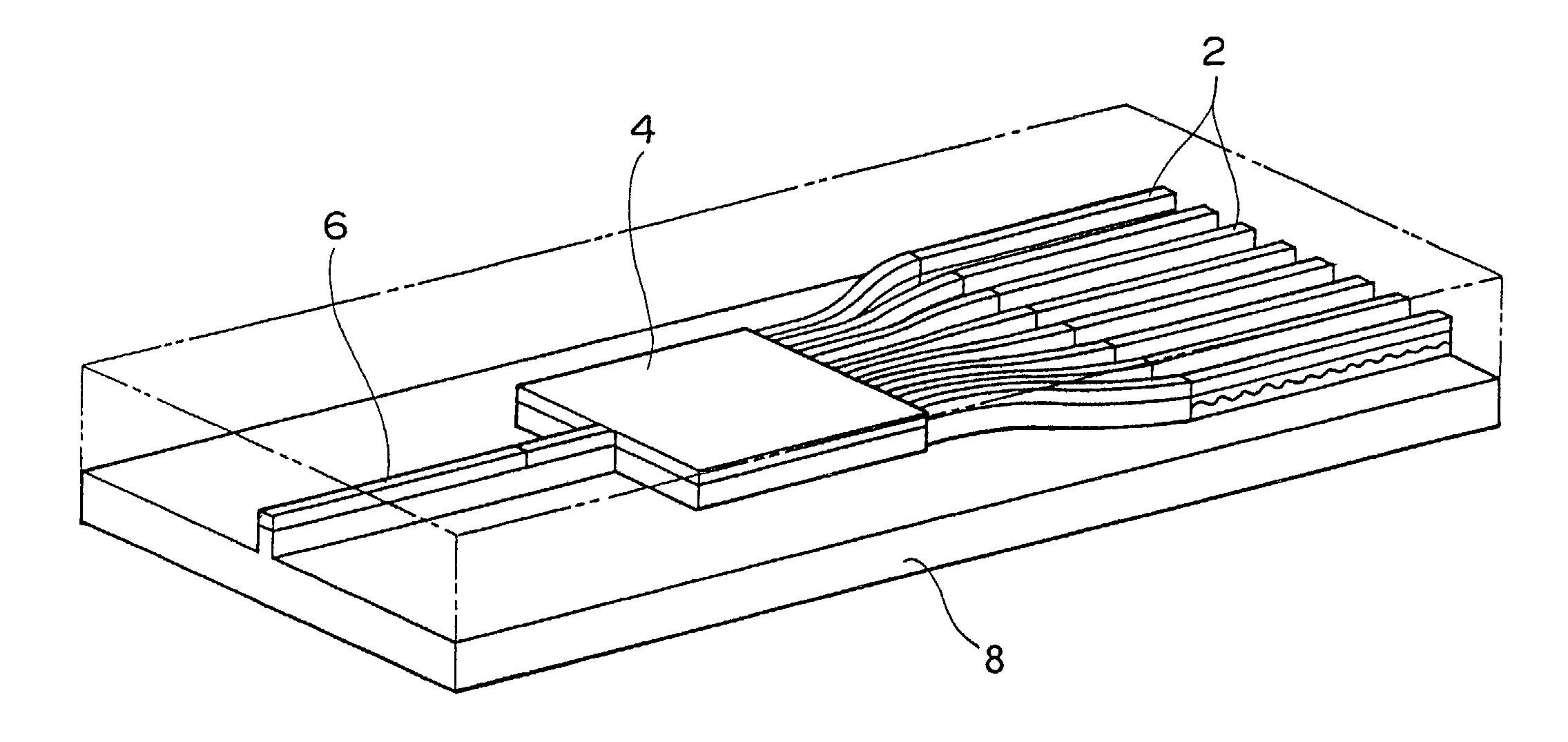
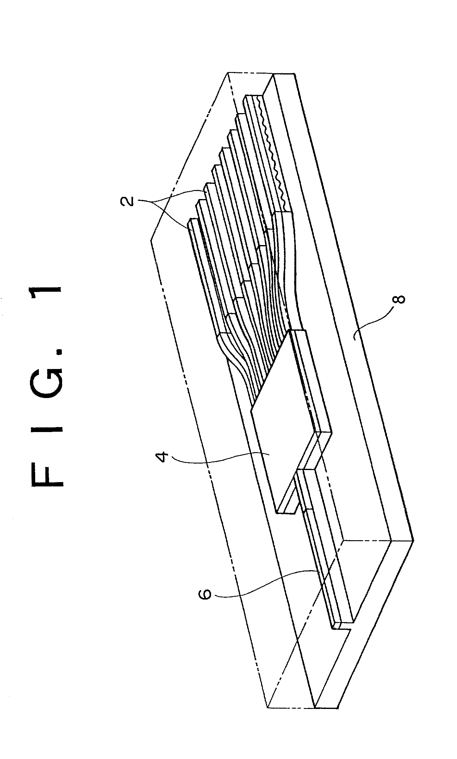
[0026]FIG. 1 is a perspective view showing a chip configuration of a tunable laser applicable to WDM. This tunable laser is configured by integrating a plurality of (e.g., eight) arrayed DFB-LD (laser diode) elements 2, an optical coupler 4, and a semiconductor optical amplifier (SOA) 6 on a common substrate 8. An optical signal output from each DFB-LD element 2 is supplied through the optical coupler 4 to the semiconductor optical amplifier 6. The optical signal is then amplified by the amplifier 6 and output from this tunable laser.

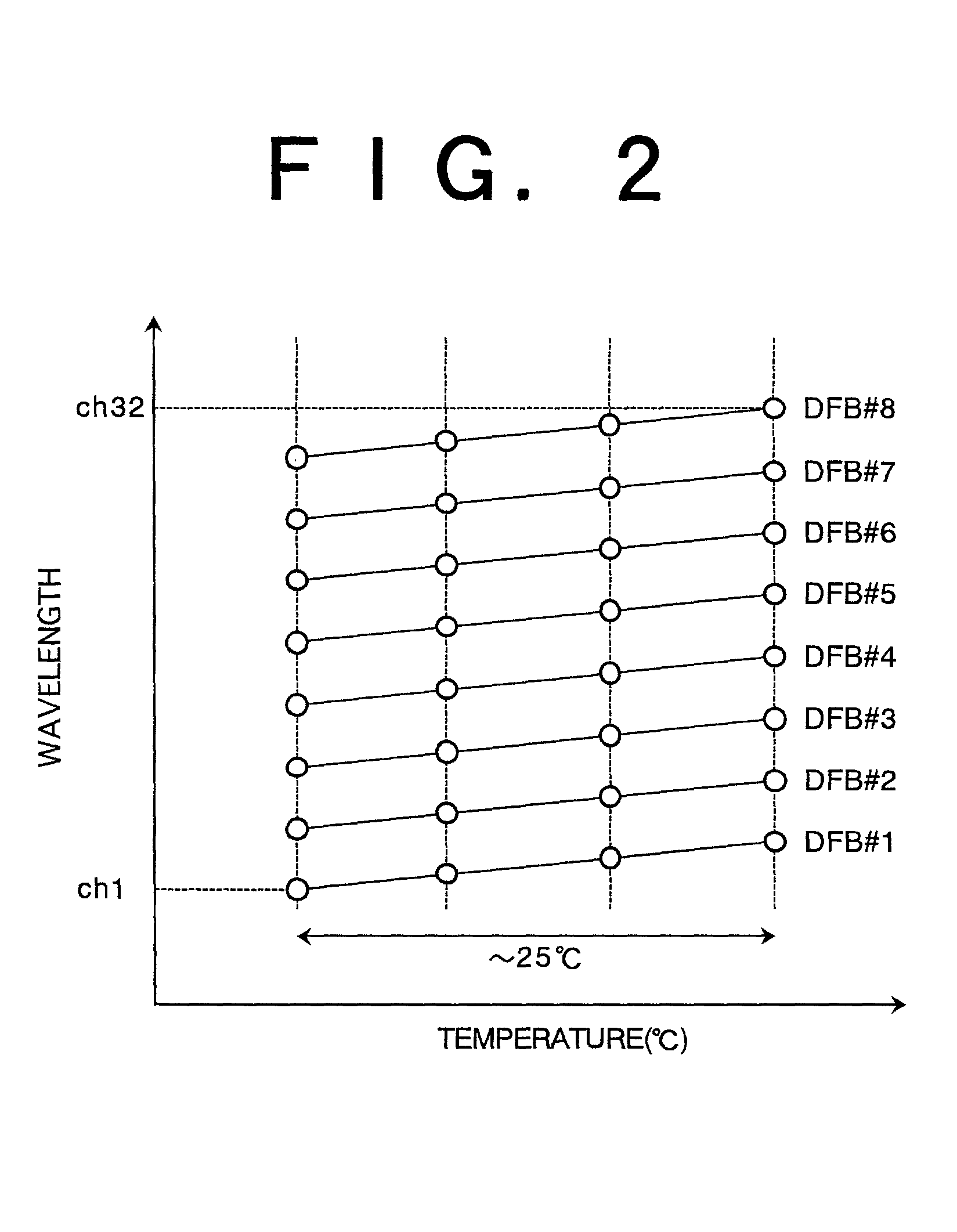
[0027]The plural DFB-LD elements 2 are designed so that their center wavelengths differ from each other with a given spacing (e.g., 400 GHz (3.2 nm)) when the elements 2 are driven at the same temperature. Each DFB-LD element 2 has temperature dependence of oscillation wavelength of about 0.08 to 0.11 nm / ° C. Accordingly, by ...


PUM


Abstract

Disclosed herein is a light source device and a wavelength control device therefor. The light source device includes a plurality of laser diodes, a temperature sensor provided in the vicinity of the plurality of laser diodes, a control loop for controlling the temperatures of the plurality of laser diodes according to an output from the temperature sensor to thereby control the oscillation wavelengths of the plurality of laser diodes, and a unit for compensating temperature control conditions for the laser diodes other than a reference laser diode selected from the plurality of laser diodes, according to a change in temperature control condition for the reference laser diode. By the compensation of the temperature control conditions, the oscillation wavelength of each laser diode can be easily stabilized to each wavelength channel of WDM.

Description

BACKGROUND OF THE INVENTION[0001]1. Field of the Invention[0002]The present invention relates to a light source device suitable for wavelength division multiplexing and a wavelength control device for the light source device.[0003]2. Description of the Related Art[0004]An optical communication system using an optical fiber transmission line is used to transmit a relatively large amount of information. A low-loss (e.g., 0.2 dB / km) optical fiber is manufactured and used as the optical fiber transmission line. In addition, an optical amplifier for compensating for losses in the optical fiber transmission line is used to allow long-haul transmission.[0005]As a technique for increasing a transmission capacity by a single optical fiber, wavelength division multiplexing (WDM) is known. In a system adopting WDM, a plurality of carriers having different wavelengths are individually modulated by data. Each modulated carrier provides one channel in the WDM system for transmitting optical signa...

Claims


Application Information

Patent Timeline
Patent Type & Authority Patents(United States)
IPC IPC(8): H01S3/04H01S3/14H01S5/068H01S5/024H01S5/026H01S5/0683H01S5/0687H01S5/12H01S5/40
CPCH04B10/572H01S5/4031H04B10/503H01S5/026H01S5/06837H01S5/0687H01S5/12H01S5/4087H01S5/4025
Inventor KAI, YUTAKAMIYATA, HIDEYUKI
Owner FUJITSU LTD
Why Eureka
Try Eureka